
Motor Current Testing: Ensuring Your Pump Isn't Overloaded
Pump motors don't announce their problems with flashing lights or alarm bells. They overheat quietly, draw excessive current silently, and fail expensively when facilities teams miss the warning signs. A central heating pump pulling 20% more current than its nameplate rating might run for months before catastrophic failure - but the damage compounds daily, driving up energy costs and accelerating wear on bearings, seals, and windings.
Motor current testing provides the diagnostic evidence heating engineers need to catch these issues early. When a Grundfos pump or any circulation system draws more amperage than specified, the root cause might be mechanical binding, incorrect voltage, phase imbalance, or system conditions forcing the pump to work harder than designed. Identifying the problem through systematic current measurement prevents premature motor failure and the costly emergency replacements that follow.
Why Pump Motor Current Matters
Every pump motor carries a nameplate rating that specifies its full load amperage (FLA) - the current draw when operating at design conditions. This figure represents the manufacturer's calculated maximum safe operating current under normal circumstances. When actual current exceeds this rating by 10-15% or more, the motor operates outside its thermal design envelope.
Excessive current generates heat that degrades winding insulation, reducing motor lifespan exponentially. A motor running 10°C above its rated temperature experiences a roughly 50% reduction in insulation life expectancy. The relationship between current, heat, and failure isn't linear - it accelerates dramatically as conditions worsen.
System Problems Revealed by Motor Overload Testing
Beyond immediate motor damage, overcurrent conditions signal system problems that affect overall heating performance. A circulator drawing excessive amperage might indicate:
- Impeller damage or debris accumulation creates mechanical resistance
- Incorrect pump sizing for actual system requirements
- Closed or partially closed isolation valves restricting flow
- System pressure conditions outside design parameters
- Bearing wear increases friction and mechanical load
- Voltage supply issues cause inefficient motor operation
Facilities managers dealing with repeated pump failures often discover the replacements weren't faulty - the system conditions causing overcurrent destroyed each successive unit until someone finally measured the current and investigated why it exceeded nameplate specifications.
Understanding Motor Nameplate Data
Before testing the current, heating engineers must interpret the information stamped on the motor nameplate. This data plate provides the baseline against which measurements are compared.
Full Load Amperage (FLA)
Full Load Amperage (FLA) represents the expected current draw when the motor operates at its rated horsepower output under design conditions. This figure assumes correct voltage supply, balanced three-phase power (where applicable), and the mechanical load the pump was designed to handle.
Service Factor
Service Factor appears on some motors as a multiplier (typically 1.15 or 1.25), indicating the motor can safely handle brief periods of overload. A motor with 10A FLA and 1.15 service factor can theoretically handle 11.5A intermittently without immediate damage - but continuous operation at this level still reduces lifespan.
Voltage and Frequency Specifications
Voltage and Frequency specifications matter critically because motors draw different currents at different voltages. A 230V motor supplied with 220V draws higher current to produce the same mechanical output. The relationship isn't proportional - a 10% voltage drop might cause a 12-15% current increase.
For three-phase motors common in commercial heating systems, the nameplate shows current per phase. Testing requires measuring all three phases because an imbalance between phases causes additional problems beyond simple overcurrent.
National Pumps and Boilers supplies pumps with clear nameplate data, but older installations or replacement motors sometimes have worn or painted-over plates. When nameplate data is unavailable, engineers must consult manufacturer specifications or calculate expected current from horsepower ratings using standard formulas.
Equipment Required for Current Testing
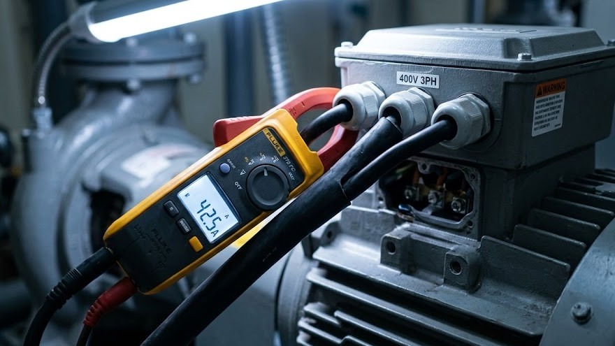
Accurate pump motor current testing demands proper instrumentation. The clamp ammeter (or clamp meter) provides non-invasive current measurement by detecting the magnetic field around a conductor without breaking the circuit.
True RMS Clamp Meters
True RMS clamp meters measure accurately even when the electrical supply contains harmonics or distortion - increasingly common in buildings with variable frequency drives and electronic equipment. Averaging meters give false readings under these conditions, potentially masking problems or suggesting issues that don't exist.
For single-phase motors typical in domestic heating systems, a basic clamp meter suffices. Testing requires measuring current on one conductor while the motor operates under normal load. Three-phase motors demand either three separate measurements (one per phase) or a three-phase clamp meter that displays all phases simultaneously.
Measurement Range and Features
Measurement range matters - the meter must handle the expected current without maxing out. Most central heating pumps draw between 0.5A and 5A, but larger commercial circulators or booster sets might pull 15-20A or more. Select a meter with an appropriate range and resolution for the application.
Additional useful features include:
- Data logging capability to track current over time and capture intermittent problems
- Inrush current measurement to assess starting conditions
- Voltage measurement to verify supply conditions during testing
- Power factor measurement for three-phase systems
Safety equipment is non-negotiable when working with electrical systems. Insulated gloves rated for the voltage, safety glasses, and adherence to lockout/tagout procedures, where appropriate, protect technicians during testing.
How to Perform Motor Current Testing
Systematic testing follows a defined procedure that ensures accurate measurements and meaningful interpretation. Heating engineers conducting motor overload testing should follow this methodology.
Step 1: Verify System Operation
Before measuring current, confirm the pump operates normally. Listen for unusual noise, check for vibration, and verify the system maintains design pressure and flow. Abnormal mechanical conditions affect current draw and should be noted before testing begins.
Step 2: Identify Electrical Supply
Locate the electrical supply to the motor. For pumps with integral controls or junction boxes, this might be inside the unit housing. Larger commercial installations typically have dedicated isolators or motor control centres. Never assume circuits are de-energised - always verify with a voltage tester.
Step 3: Access Conductors
The clamp meter must encircle a single conductor to measure current accurately. Clamping around a cable containing both supply and return conductors (like a standard flex) produces zero reading because the magnetic fields cancel. Access individual conductors at:
- Motor terminal box where individual phase wires connect
- Isolator terminals (with appropriate safety precautions)
- Junction boxes or control panels
- Supply cables where individual conductors are accessible
For single-phase motors, measure the live conductor. For three-phase motors, measure all three phases individually.
Step 4: Take Measurements
With the motor running under normal operating conditions, clamp the meter around the conductor and record the reading. For accurate results:
- Ensure the conductor sits centred in the clamp jaw
- Hold the meter steady - movement can affect readings
- Take multiple measurements over 30-60 seconds to capture variation
- Record maximum, minimum, and average readings
- Note any fluctuation or instability in the current
For three-phase motors, measure each phase sequentially and record all values. Significant variation between phases (more than 5-10%) indicates supply problems or motor issues requiring investigation.
Step 5: Measure Supply Voltage
Current readings mean little without corresponding voltage measurements. Use a multimeter to check the voltage at the motor terminals while the pump operates. Compare actual voltage to nameplate specifications.
Step 6: Calculate and Compare
Compare the measured current to the nameplate FLA. Calculate the percentage difference:
(Measured Current - Nameplate FLA) / Nameplate FLA × 100 = % Deviation
A pump drawing 4.2A when the nameplate specifies 3.5A, FLA shows 20% overcurrent - a significant deviation requiring immediate investigation.
Interpreting Test Results
Raw current measurements require context and interpretation to guide corrective action. Understanding what different readings indicate helps heating engineers diagnose problems accurately through pump motor current testing.
Current Within 5% of FLA
Current within 5% of FLA represents normal operation. Minor variations result from voltage fluctuation, measurement accuracy, and differences between actual system conditions and the test conditions under which FLA was determined. No action required beyond routine monitoring.
Current 5-15% Above FLA
Current 5-15% above FLA suggests developing problems or suboptimal conditions. Investigation should focus on:
- System pressure and flow conditions
- Valve positions and pipe restrictions
- Pump performance curve versus actual operating point
- Supply voltage verification
- Recent system changes
This range warrants attention but typically doesn't require immediate shutdown. Schedule corrective action and increase monitoring frequency.
Current 15-25% Above FLA
Current 15-25% above FLA indicates serious problems requiring prompt action. The motor operates outside its thermal design parameters, accelerating insulation degradation and increasing failure risk. Identify and correct the root cause within days, not weeks.
Current Exceeding 25% Above FLA
Current exceeding 25% above FLA represents emergency conditions. The motor faces imminent failure, and continued operation risks catastrophic damage, including winding burnout, bearing seizure, or fire. Shutdown and investigation should occur immediately.
Current Significantly Below FLA
Current significantly below FLA (more than 20% low) might seem positive, but often indicates problems:
- Pump running against a closed or partially closed valve
- Impeller damage reduces mechanical load
- Loss of time or air lock is preventing normal operation
- Incorrect motor replacement (oversized for the application)
For three-phase motors, phase imbalance exceeding 5-10% between the highest and lowest phase current indicates supply problems or motor winding issues. Even when the average current appears normal, an imbalance causes circulating currents that generate excessive heat and reduce motor life.
Common Causes of Excessive Motor Current
When motor overload testing reveals overcurrent conditions, systematic diagnosis identifies the root cause. The most frequent culprits fall into several categories.
Mechanical Problems
Bearing wear increases friction and mechanical resistance, forcing the motor to work harder. As bearings degrade, current draw increases gradually - often by 10-15% before noise or vibration becomes obvious. Regular current testing catches bearing problems before catastrophic failure.
Impeller damage or debris accumulation creates imbalance and resistance. A DHW pump with scale buildup on the impeller or a central heating circulator with corrosion debris in the volute draws excessive current while delivering reduced flow.
Shaft misalignment between motor and pump (in coupled designs) generates side loading on bearings and uneven mechanical stress. Current increases as the motor fights the misalignment.
Hydraulic Conditions
Operating outside the pump's design envelope forces excessive current draw. A pump selected for 15 metres head but installed in a system requiring 20 metres works harder, drawing more current while delivering inadequate performance. The motor might operate within its service factor, but well above FLA.
Closed or restricted valves create back pressure that increases motor load, particularly in positive displacement and some centrifugal designs. Technicians sometimes find isolation valves partially closed after maintenance work, causing chronic overcurrent conditions.
Deadheading - running a pump against a closed discharge - represents the most severe hydraulic condition. Some pump types draw maximum current at shutoff, potentially exceeding motor capacity within seconds.
Electrical Supply Issues
Low voltage forces motors to draw higher current to produce the rated mechanical output. The relationship isn't linear - a 10% voltage drop might cause a 12-15% current increase. Buildings with undersized electrical supply, long cable runs, or voltage drop under load often experience chronic motor overcurrent.
Phase imbalance in three-phase supplies causes additional current draw and circulating currents between phases. Even 3-4% voltage imbalance can increase current significantly and reduce motor efficiency.
Incorrect motor winding connections (delta versus wye) or wrong voltage tap selection cause dramatic overcurrent. A 230/400V motor connected in delta configuration to a 400V supply draws approximately 73% more current than designed.
Motor Degradation
Winding insulation breakdown causes internal short circuits that increase current draw while reducing mechanical output. This typically occurs gradually as insulation ages, but can accelerate dramatically if moisture or contamination enters the motor.
Rotor bar damage in squirrel cage motors creates asymmetry that increases current and reduces efficiency. This often manifests as fluctuating current readings rather than steady overcurrent.
Preventive Testing Schedules
Reactive current testing - measuring only when problems occur - misses the opportunity for predictive maintenance. Establishing regular testing schedules catches developing issues before failure.
Testing Frequency Recommendations
Critical heating systems serving hospitals, care facilities, or commercial buildings where downtime causes significant disruption: quarterly testing provides trend data that predicts failures months in advance. A pump showing gradual current increase from 3.5A to 3.8A to 4.1A over successive quarters signals developing problems requiring investigation.
Standard commercial installations: Semi-annual testing, typically aligned with seasonal system maintenance before heating season and again mid-winter during peak operation. This schedule balances labour costs against risk management.
Domestic and smaller commercial systems: Annual testing, combined with general system service and inspection. However, any pump with a history of problems or operating in demanding conditions warrants more frequent monitoring.
Additional Testing Triggers
Testing should always follow:
- Motor replacement or major repair
- System modifications affecting pump load
- Electrical supply changes or upgrades
- Unexplained performance degradation
- Increased energy consumption
- Unusual noise or vibration
Maintaining test records enables trend analysis that reveals patterns invisible in single measurements. A pump consistently drawing 3.7A operates differently than one varying between 3.2A and 4.3A - even if both average similar values.
Integration with Broader System Diagnostics
Motor current testing delivers maximum value when integrated with comprehensive system diagnostics. Current measurements combined with pressure, temperature, and flow data paint a complete picture of pump and system health.
Diagnostic Correlation
A circulator drawing excessive current while delivering normal flow and pressure indicates motor or bearing problems. The same overcurrent with reduced flow suggests hydraulic issues - blocked strainer, damaged impeller, or system restrictions. Overcurrent with normal flow but excessive pressure might indicate incorrect pump selection or system design problems.
Temperature measurements at the motor housing, bearings, and pump body provide corroborating evidence. A motor drawing 20% overcurrent should run noticeably hotter than specification. If the current is high but the temperature remains normal, suspect measurement error or intermittent conditions.
Vibration analysis catches mechanical problems that current testing alone might miss. Bearing wear shows in both increased current and specific vibration frequencies. Impeller damage creates vibration signatures before the current increase becomes significant.
Energy monitoring provides the business case for corrective action. A pump drawing 20% overcurrent typically consumes 15-25% more electricity than necessary. Calculating annual waste from overcurrent often justifies repair or replacement costs within months.
Corrective Actions Based on Test Results
Identifying overcurrent conditions is only valuable if followed by effective corrective action. The appropriate response depends on the root cause and severity.
Immediate Actions for Severe Overcurrent (>25% Above FLA)
Shut down the pump and investigate before resuming operation. Check for:
- Closed or restricted valves that should be open
- Mechanical binding or seized components
- Obvious electrical supply problems
- Signs of motor overheating or damage
If no immediate cause is apparent, operate the pump only long enough to maintain minimum system function whilst arranging emergency repair or replacement.
Short-Term Actions for Moderate Overcurrent (15-25% Above FLA)
Reduce operating hours where possible to limit thermal stress whilst investigating the root cause. Verify:
- All system valves are correctly positioned
- Supply voltage meets specifications
- No recent system changes that might affect pump load
- The pump operates on its performance curve at the design point
Schedule corrective maintenance within days, not weeks. The motor operates outside safe parameters, and failure risk increases daily.
Medium-Term Actions for Minor Overcurrent (5-15% Above FLA)
Investigate system conditions and mechanical health. Consider:
- Bearing inspection and lubrication
- Impeller cleaning or replacement
- System balancing and pressure verification
- Electrical supply testing and correction
Schedule corrective work during the next planned maintenance window, but within weeks rather than months. Increase monitoring frequency to track whether conditions worsen.
Specific Corrections
For bearing wear: Replace bearings before failure. Many pump designs use standard bearing sizes available from pump valve and component suppliers, making replacement straightforward.
For hydraulic problems: Reselect the pump if the original specification was incorrect. Clean or replace impellers if damaged. Remove restrictions and verify system design matches pump capabilities.
For electrical issues: Correct supply voltage through cable upgrades, transformer tap adjustment, or voltage regulation. Balance three-phase supplies. Verify motor connections match the supply voltage.
For motor degradation: Replace the motor. Rewinding is rarely cost-effective for small motors under 5HP. Larger motors might justify professional rewinding from specialist motor repair shops.
Conclusion
Motor current testing transforms pump maintenance from reactive crisis management to predictive reliability engineering. A heating engineer with a clamp meter and five minutes can gather diagnostic data that predicts failures months in advance, prevents costly emergency replacements, and optimises system energy consumption.
The distinction between a pump operating within design parameters and one slowly destroying itself often comes down to 0.5-1.0 amperes - a difference invisible without measurement but catastrophic over time. Regular pump motor current testing catches these deviations early when corrective action is simple and inexpensive.
For facilities teams managing multiple pumps across commercial heating systems, establishing routine motor overload testing protocols delivers a measurable return on investment through extended equipment life, reduced energy costs, and elimination of emergency failures during peak heating season.
Whether specifying new equipment, diagnosing existing problems, or implementing predictive maintenance programmes, contact us for technical guidance on pump selection, system diagnostics, and maintenance best practices that keep heating systems operating reliably and efficiently.