
Post-Installation Performance Testing: Key Measurements to Take
Installing a new pump or heating system represents a significant investment for any commercial facility or residential property. Yet many installers complete the physical installation and walk away without verifying that the equipment performs as specified. This oversight leads to inefficient operation, premature equipment failure, and costly callbacks that could have been prevented with proper commissioning procedures.
Pump performance testing after installation serves as the final quality checkpoint - the moment when theoretical system design meets operational reality. Without these measurements, installers cannot confirm that flow rates match calculations, that pressures fall within acceptable ranges, or that energy consumption aligns with manufacturer specifications. National Pumps and Boilers supplies equipment to contractors who understand that professional commissioning separates competent installations from exceptional ones.
The measurements taken during post-installation testing provide baseline data for future maintenance decisions, warranty claims, and troubleshooting. They also verify compliance with Building Regulations Part L requirements for energy efficiency and demonstrate due diligence should performance issues arise later. This article outlines the essential measurements that heating engineers and mechanical services contractors should record after every pump and heating system installation.
Flow Rate Verification
Flow rate represents the most fundamental performance metric for any pumping system. The actual flow delivered must match the design calculations that determined pipe sizing, radiator outputs, and boiler capacity. Measuring flow rate accurately requires proper equipment and methodology rather than assumptions based on pump curves.
Methods for Accurate Flow Measurement
For central heating pumps installations, ultrasonic flow meters provide non-invasive measurement without disrupting the system. Clamp-on transducers measure flow velocity through pipe walls, calculating volumetric flow based on pipe dimensions. These instruments deliver accuracy within ±2% when properly calibrated and positioned on straight pipe sections away from bends or valves.
Differential pressure flow meters offer an alternative approach, measuring the pressure drop across a known restriction to calculate flow rate. Many modern circulators include integrated flow measurement capabilities, displaying real-time flow data through their control interfaces. When using pump-integrated measurements, verify accuracy by cross-checking with an independent flow meter during initial commissioning.
Record flow measurements at multiple operating conditions - minimum flow during mild weather, design flow at peak heating demand, and any intermediate set points programmed into the control system. Compare these measurements against the original system calculations, accepting variations within ±10% as normal for most applications. Significant deviations indicate undersized pipework, excessive system resistance, or incorrect pump selection that requires investigation.
Differential Pressure Analysis
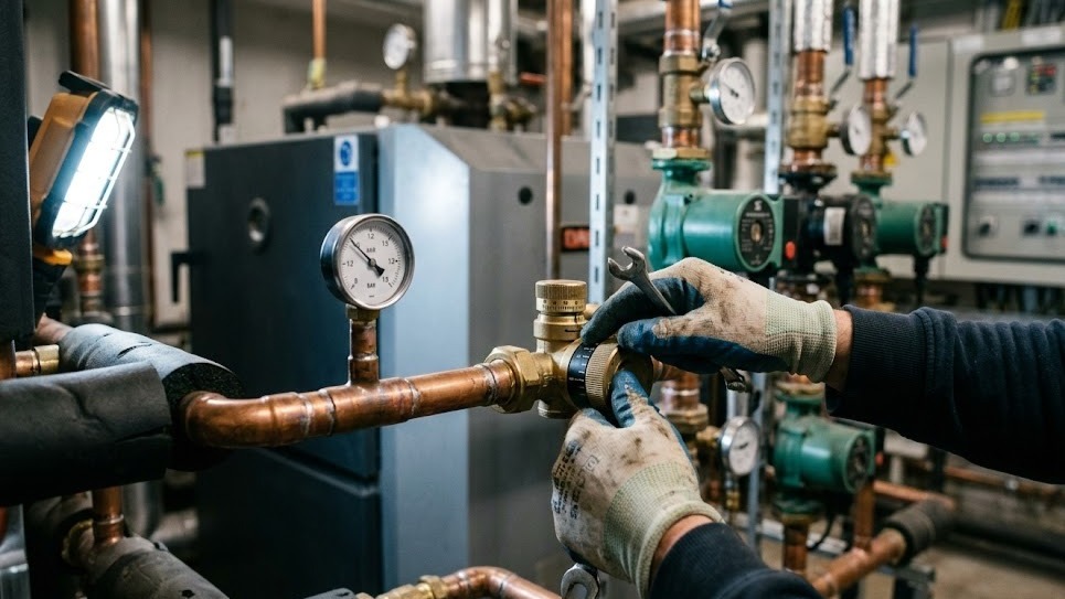
Differential pressure measurements reveal whether the pump delivers sufficient head to overcome system resistance while avoiding excessive pressure that wastes energy. Measure pressure at the pump inlet and outlet using calibrated gauges or digital manometers, recording the difference as the pump's operating head.
Plotting Performance Against Manufacturer Curves
Plot this measured differential pressure against the recorded flow rate on the pump performance curve provided by manufacturers like Grundfos pumps or Wilo circulators. The operating point should fall within the pump's preferred operating range - typically between 40% and 90% of maximum flow. Operating outside this range indicates poor pump selection or system design issues requiring correction.
For variable speed pumps controlled by differential pressure sensors, verify that the control set point matches the system's actual requirements. Many installers accept default factory settings without optimisation, resulting in excessive pump speed and wasted energy. Reduce the differential pressure set point incrementally while monitoring system performance, finding the minimum pressure that maintains adequate flow to all terminal units.
Component Pressure Drop Measurements
Measure differential pressure across critical system components, including heat exchangers, filters, and control valves. Excessive pressure drop indicates fouling, undersizing, or partially closed isolation valves. Document these baseline measurements for comparison during future maintenance visits, as increasing pressure drop signals developing problems before they cause system failure.
Temperature Measurements Across System Components
Temperature measurements validate heat transfer performance and identify circulation problems that reduce system efficiency. Measure supply and return temperatures at the boiler, recording the temperature differential (ΔT) that indicates heat delivery to the system. Most heating systems target a ΔT of 10-20°C depending on application and emitter type.
Interpreting Temperature Differentials
A smaller than expected ΔT suggests excessive flow rate through the boiler - the water moves too quickly to absorb heat effectively. This condition wastes pump energy and may cause boiler cycling. Conversely, an excessive ΔT indicates insufficient flow, risking boiler overheating and thermal stress on components. Adjust pump speed or system balancing to achieve the design ΔT specified by the boiler manufacturer.
Measure temperatures at multiple points throughout the distribution system, comparing temperatures at the nearest and furthest radiators or heat emitters. Significant temperature variation indicates poor system balancing, with some circuits receiving excessive flow while others remain starved. Use lockshield valve adjustments to balance the system, achieving similar temperature drops across all circuits.
DHW System Temperature Verification
For DHW pumps serving domestic hot water systems, measure temperatures at the cylinder outlet, at the furthest tap, and at the return to the cylinder. The temperature at the furthest tap should reach 50°C within 30 seconds of opening to satisfy Building Regulations requirements for water efficiency. Lower temperatures or longer wait times indicate inadequate circulation pump sizing or poor system design.
Electrical Consumption and Power Factor
Electrical measurements verify that pump motors operate within their rated parameters and identify opportunities for energy optimisation. Testing pump efficiency requires a power quality analyser or clamp meter to measure voltage, current, power consumption, and power factor at the pump electrical connection point.
Analyzing Power Consumption Data
Compare measured power consumption against the pump manufacturer's specifications at the recorded flow and pressure conditions. Power consumption exceeding specifications by more than 10% suggests mechanical problems such as bearing wear, impeller damage, or motor winding issues requiring investigation. Lower than expected power consumption may indicate cavitation, air entrainment, or operation outside the pump's design range.
Power factor measurements reveal the efficiency of electrical energy conversion. Most modern pump motors achieve power factors above 0.85 when operating near their design point. Lower power factors indicate inefficient motor operation, increasing electricity costs and potentially incurring power factor penalties from electricity suppliers. Variable speed drives can improve power factor while providing flow control, making them attractive upgrades for older installations.
Variable Speed Performance Documentation
Record electrical measurements at multiple operating speeds for variable speed pumps, documenting the relationship between flow rate and power consumption. This data demonstrates the energy savings achieved through variable speed operation compared to fixed-speed alternatives, providing justification for the additional equipment cost and supporting ErP compliance documentation.
System Pressure and Expansion Vessel Function
System pressure measurements confirm proper filling and expansion vessel sizing. Measure static pressure with the system cold and all pumps off, verifying that pressure falls within the range specified by the boiler manufacturer - typically 1.0 to 1.5 bar for domestic systems and higher for commercial installations.
Dynamic Pressure Testing
Start the circulation pumps and record the pressure change. A small pressure increase of 0.1 to 0.3 bar is normal, but larger increases suggest undersized pipework or partially closed valves creating excessive resistance. Measure pressure at multiple points throughout the system, identifying any significant pressure drops that indicate flow restrictions.
Heat the system to operating temperature and monitor pressure increase. The pressure rise should remain within acceptable limits, with the system pressure staying below the pressure relief valve setting. Excessive pressure increase indicates undersized expansion vessels that cannot accommodate the additional water volume created by thermal expansion.
Expansion Vessel Pre-Charge Verification
Verify expansion vessel pre-charge pressure using a tyre pressure gauge on the vessel's Schrader valve with the system drained or isolated. The pre-charge should match the system static pressure minus 0.2 bar. Incorrect pre-charge pressure prevents proper vessel operation, causing pressure fluctuations and potential system damage. Adjust the pre-charge using a hand pump or by releasing air until the correct pressure is achieved.
Noise and Vibration Assessment
Acoustic and vibration measurements identify installation problems that lead to occupant complaints and premature equipment failure. While subjective assessment provides initial screening, quantitative measurements using sound level meters and vibration analysers document baseline conditions for future comparison.
Sound Level Documentation
Measure sound levels at one metre from the pump in multiple directions, recording both overall sound pressure level and frequency spectrum. Compare measurements against manufacturer specifications and Building Regulations Approved Document E requirements for noise control. Excessive noise indicates cavitation, air entrainment, bearing wear, or inadequate vibration isolation.
Vibration measurements using accelerometers mounted on pump casings and connected pipework reveal mechanical problems invisible to other testing methods. Elevated vibration at running speed frequency indicates imbalance or misalignment. Vibration at bearing frequencies suggests bearing wear requiring attention. High-frequency vibration often indicates cavitation or turbulent flow conditions.
Multi-Condition Testing
Assess noise and vibration with the pump operating at multiple speeds and flow conditions. Some problems only manifest at specific operating points, remaining hidden during brief commissioning checks. Document any unusual sounds such as rattling, grinding, or whistling that suggest specific mechanical problems requiring investigation.
Control System Verification
Modern heating systems incorporate sophisticated controls that require verification beyond simple on/off testing. Confirm that temperature sensors provide accurate readings by comparing displayed temperatures against calibrated reference thermometers at multiple measurement points. Sensor errors of more than ±2°C indicate calibration drift or installation problems requiring correction.
Control Sequence Testing
Test control sequences by simulating various operating conditions, verifying that pumps, valves, and boilers respond appropriately. Gradually increase heating demand and confirm that the system modulates smoothly without hunting or cycling. Test safety interlocks including high temperature cutouts, low water pressure switches, and frost protection functions.
For systems with weather compensation or load-based controls, verify that the compensation curve matches the building's thermal characteristics. Monitor system operation over several days with varying outdoor temperatures, adjusting control parameters to optimise comfort while minimising energy consumption. Document the final control settings as part of the commissioning record.
BMS Integration Verification
Verify that any building management system integration functions correctly, with accurate data transmission and proper alarm handling. Test remote monitoring capabilities if installed, confirming that performance data reaches the intended recipients and that remote control functions operate as designed.
Documentation and Baseline Recording
Comprehensive documentation transforms commissioning measurements from a one-time exercise into a valuable maintenance tool. Create a commissioning report that includes all measurements, instrument calibration certificates, and comparison against design specifications. Photograph instrument displays showing key measurements, providing visual evidence of system performance.
Creating Performance Curves
Generate performance curves plotting actual flow versus pressure measurements against manufacturer pump curves. These curves provide immediate visual confirmation of proper pump selection and system design. Include them in the commissioning documentation along with electrical measurements and temperature profiles.
Provide the building owner or facility manager with a summary document highlighting key performance metrics in accessible language. Include recommendations for ongoing monitoring and maintenance intervals based on the installed equipment. This documentation demonstrates professional competence and provides clear guidance for future service work.
Record Storage and Accessibility
Store commissioning records in multiple formats - paper copies in the plant room, digital files with the customer, and archived versions with the installing contractor. These records prove invaluable when troubleshooting future problems, processing warranty claims, or planning system modifications. They also demonstrate compliance with Building Regulations commissioning requirements during building inspections.
Conclusion
Post-installation pump performance testing transforms a physical installation into a verified, documented system ready for reliable service. The measurements outlined above provide objective evidence that equipment performs as designed, identify problems requiring correction before they escalate, and establish baseline data for future maintenance decisions. Testing pump efficiency through comprehensive commissioning procedures allows heating engineers and mechanical contractors to differentiate themselves through professional competence and reduce costly callbacks.
The testing procedures described require proper instrumentation, technical knowledge, and attention to detail - qualities that define professional mechanical services contractors. While these measurements add time to installation projects, they prevent far more time spent diagnosing mysterious performance problems or defending against complaints about inadequate heating.
For guidance on pump selection, system design, or technical specifications, contact us for expert advice tailored to specific applications and performance requirements.