
Pressurisation Unit Alarms: What Each One Means and How to Respond
Pressurisation unit alarm codes represent critical warnings that demand systematic investigation from heating engineers. These devices maintain optimal system pressure across commercial and large domestic heating installations, and when alarm conditions activate, underlying causes range from minor sensor calibration drift to serious failures that risk equipment damage or complete system shutdown. The distinction between silencing an alarm and diagnosing its root cause separates competent maintenance from temporary fixes that allow the same fault to recur within days or weeks.
Modern pressurisation units integrate sophisticated monitoring systems tracking pressure, temperature, pump performance, and vessel integrity. Each pressurisation unit alarm code corresponds to specific operational parameters falling outside acceptable ranges. Understanding these codes in the context of the complete system - rather than in isolation - enables accurate diagnosis that identifies whether the problem lies in the pressurisation unit itself or in the wider heating system it serves.
Understanding Pressurisation Unit Functions
Pressurisation units serve a fundamental role in closed-loop heating systems by maintaining consistent pressure regardless of temperature fluctuations. As system water heats and expands, the unit absorbs volume increase through an expansion vessel whilst maintaining pressure within the design envelope specified by British Standards. When water cools and contracts, the unit reintroduces water to prevent vacuum formation and the air ingress that causes cold spots, pump cavitation, and corrosion acceleration throughout the circuit.
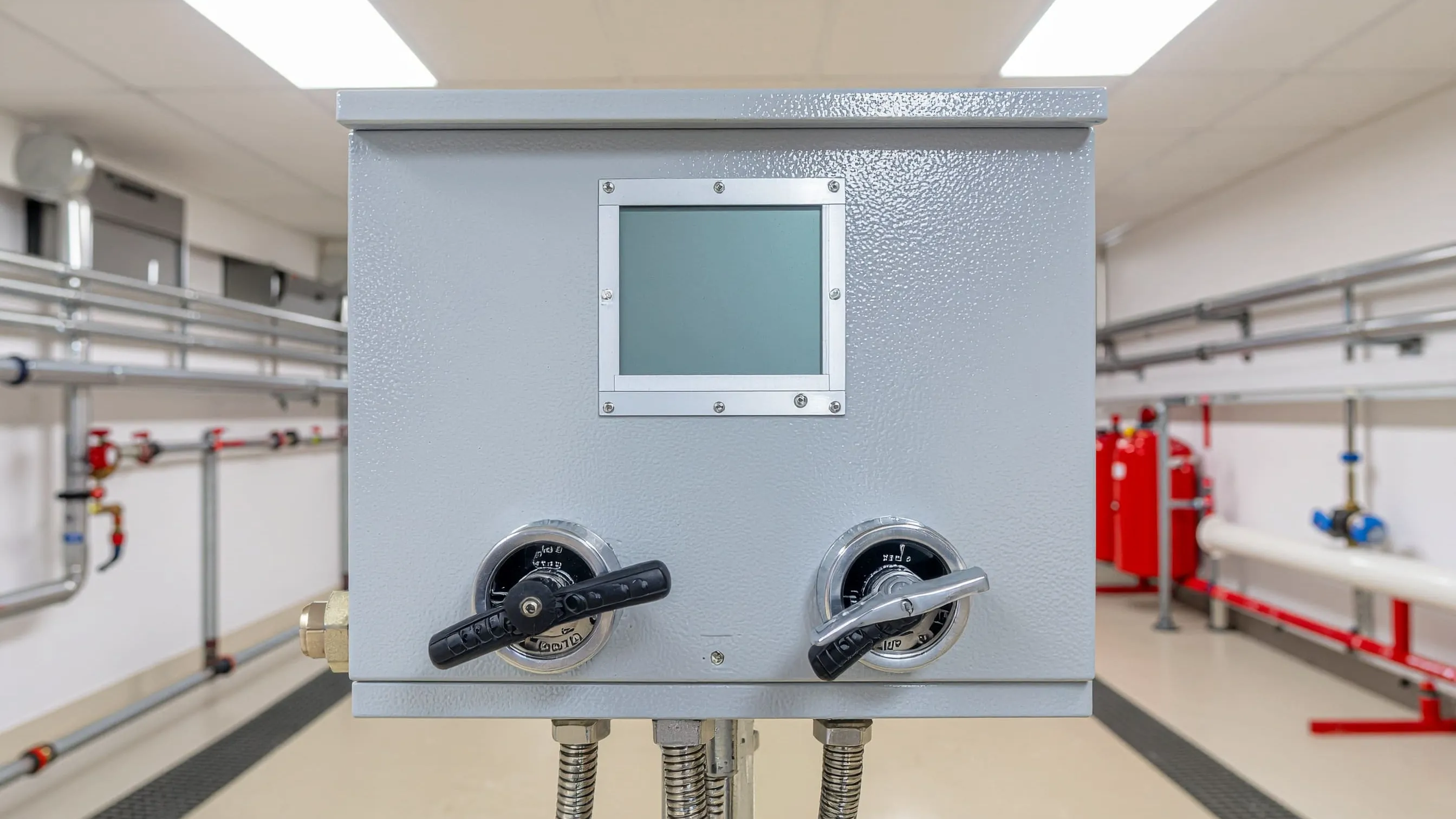
The typical pressurisation unit comprises one or more pumps, an expansion vessel with diaphragm or bladder, pressure sensors, a control panel, and a safety relief valve. The control system continuously monitors pressure via transducers, activating pumps when pressure drops below the lower setpoint and triggering pressurisation unit alarm codes when conditions exceed programmed parameters. This automated response prevents the dangerous pressure losses that cause pump damage or the excessive pressures that stress pipework joints and heat exchangers beyond their rated capacity.
For Grundfos pressurisation units with dual pump configurations, the control system manages pump alternation to equalise running hours, monitors individual pump performance, and activates the standby pump automatically when the duty pump fails - a redundancy feature whose alarm system provides detailed fault differentiation between pump A failure, pump B failure, and complete pressurisation loss.
Common Alarm Codes and Their Meanings
Low Pressure Alarms
Low pressure alarms activate when system pressure falls below the minimum threshold, typically set 0.2–0.3 bar above static fill pressure to provide a buffer before conditions become damaging. This alarm indicates water loss through leaks, expansion vessel pre-charge failure, or pump malfunction preventing pressure maintenance. Low pressure conditions require immediate investigation because continued operation risks pump cavitation and progressive air entrainment throughout the circuit that creates cold spots, corrosion, and further pressure instability.
For central heating systems where a low pressure alarm has activated, the priority sequence is: verify actual system pressure with an independent gauge, check for visible leaks at accessible pipework and valve connections, then assess expansion vessel pre-charge - these three checks resolve the majority of low pressure alarm causes without specialist equipment.
High Pressure Alarms
High pressure alarms trigger when pressure exceeds the upper setpoint, typically configured 0.5–1.0 bar below the safety valve setting to provide a warning margin before discharge occurs. Causes include vessel membrane rupture eliminating expansion capacity, incorrect pre-charge pressure preventing the vessel accepting water, control system failure maintaining constant pump operation, or simply inadequate expansion vessel capacity for the actual system water volume. High pressure conditions demand urgent response as they indicate proximity to safety valve discharge or imminent stress damage to system components.
Pump Failure Indicators
Pump failure indicators signal when the pressurisation pump fails to start, draws excessive current, or runs without achieving a measurable pressure increase. These alarms point to electrical supply problems, mechanical seizure from bearing failure or scale accumulation, impeller blockage from magnetite or debris, or motor winding failure from overheating or insulation breakdown. Pump faults eliminate the unit's ability to maintain pressure, making this among the most critical pressurisation unit alarm codes requiring same-day attention in occupied buildings.
Sensor Fault Warnings
Sensor fault warnings appear when pressure transducers provide readings outside physically possible ranges or when the control system detects wiring discontinuity. These alarms may not reflect actual pressure problems but indicate the control system has lost reliable pressure monitoring capability - which is itself a serious fault even if system pressure happens to be correct at the moment of detection. Sensor faults require verification of actual system pressure using independent calibrated gauges before dismissing the alarm, as genuine pressure problems can coincide with sensor failures in ageing systems.
Temperature-Related Alerts
Temperature-related alerts occur on units incorporating thermal sensors monitoring pump motor temperature or system water temperature at the pressurisation connection point. Overheating pump motors indicate bearing wear increasing mechanical friction, inadequate ventilation around the unit in congested plant rooms, or excessive cycling frequency from an undersized expansion vessel. High system water temperature warnings suggest circulation problems or boiler control faults that affect pressurisation unit operation indirectly by increasing thermal stress on vessel membranes.
Immediate Response Procedures
When any pressurisation unit alarm code activates, confirming actual system conditions takes priority over assuming sensor accuracy or acting on displayed readings alone. Install an independent pressure gauge at the nearest test point and compare readings against the control panel display. This verification distinguishes genuine pressure problems from sensor or control faults generating false alarms - a distinction that determines whether the response involves system isolation or simply sensor replacement.
Safety protocols require that high pressure alarms exceeding 0.3 bar above the upper setpoint trigger immediate system isolation until the cause is identified. Close isolation valves to the pressurisation unit and observe whether system pressure stabilises or continues rising - this test identifies whether the pressurisation unit or a separate system component causes the overpressure condition. Document alarm conditions thoroughly before resetting: record the exact pressurisation unit alarm code, displayed pressure reading, system temperature, time of activation, and any relevant recent system history that might indicate the onset of the fault.
Physical inspection during initial response checks for water discharge from the safety relief valve body or discharge pipework, indicating recent overpressure events that may have already occurred before the alarm activated. Inspect pump glands and vessel connections for moisture or corrosion staining. Feel the expansion vessel surface - a uniformly warm vessel suggests membrane failure allowing heated system water to fill the entire vessel interior where nitrogen gas should be.
Troubleshooting Low Pressure Alarms
Systematic leak detection begins with all visible pipework joints, radiator connections, valve glands, and equipment casings. Inspect beneath boilers and around pump locations where leaks commonly develop and drip onto floors. For concealed pipework within floor or ceiling voids, the pressurisation unit's make-up water counter - fitted on many commercial units - provides quantitative evidence: a unit replenishing more than 1% of system volume weekly indicates active leakage requiring leak location and repair rather than continued topping up.
Expansion vessel pre-charge verification is required whenever low pressure alarms persist despite apparent leak-free inspection. Isolate the vessel from the system, confirm system pressure has reached zero, then measure the air pre-charge at the Schrader valve. For Mikrofill pressurisation units, technical documentation specifies exact pre-charge values for each model variant - low pre-charge causes the vessel to waterlog, eliminating expansion capacity and creating a feedback loop where the make-up pump replenishes water whilst the waterlogged vessel cannot buffer thermal expansion, generating both low pressure alarms when cold and high pressure conditions when hot.
Pump operation assessment involves observing whether pumps activate when pressure drops to the lower setpoint and whether pumping achieves measurable pressure recovery. A pump running without raising pressure indicates mechanical problems - worn impeller, damaged seals allowing internal recirculation, or an air lock preventing priming. System refill after low pressure alarms must proceed slowly whilst venting high points to prevent air entrainment, with pressure stability monitored through several complete heating cycles before considering the alarm condition fully resolved.
Addressing High Pressure Alarms
Relief valve inspection becomes the first priority when high pressure alarms activate. Check whether the valve has discharged recently by examining the valve body and discharge pipework for water staining or active dripping. Test the relief valve manually by briefly lifting the test lever to confirm free movement and proper reseating - a valve that does not reseat cleanly after manual testing requires replacement before the system is returned to service. A stuck-closed valve eliminates the last line of overpressure protection.
Vessel membrane integrity assessment with the system cold and at normal fill pressure provides definitive diagnosis of expansion vessel failure. Press the Schrader valve core: water discharge confirms membrane rupture allowing system water into the nitrogen chamber, eliminating expansion capacity. For Wilo pressurisation systems incorporating advanced vessel monitoring, the vessel condition data available through the diagnostic interface may identify membrane degradation before complete failure - an early warning capability that enables planned replacement rather than emergency response.
Expansion capacity assessment addresses the scenario where all mechanical components function correctly but the installed vessel volume is inadequate for the actual system water content. Calculate the required expansion volume using total system water content, operating temperature range, cold fill pressure, and safety valve setting. When calculations confirm the installed vessel is undersized, additional vessel capacity installation provides a permanent solution. Adjusting pressure setpoints to mask inadequate expansion capacity is not an acceptable response to high pressure alarms caused by vessel undersizing.
Pump and Motor Fault Responses
Electrical supply verification begins with confirming correct voltage at the pressurisation unit's main supply terminals using a calibrated multimeter. Voltage should remain within ±6% of nominal during pump operation - low voltage causes motors to draw excessive current whilst delivering reduced output, triggering thermal overload protection that manifests as pump failure alarms. Check all fuses, circuit breakers, and contactors for signs of overheating, discolouration, or poor mechanical connections that increase circuit resistance.
For DAB pump assemblies within pressurisation units, impeller blockage diagnosis involves removing the pump head and inspecting the impeller for magnetite accumulation, corrosion deposits, or physical damage. Systems with inadequate water quality maintenance develop black iron oxide sludge that restricts impeller rotation progressively until pump failure alarms activate. Thoroughly clean the impeller and pump chamber, then address system water quality - black or brown system water requires chemical cleaning and inhibitor dosing before pump reassembly and return to service.
Motor overload conditions present when thermal protection devices trip repeatedly during normal operation. Measure motor running current and compare against nameplate ratings - current exceeding rated values by more than 10% indicates mechanical or electrical problems requiring correction. Bearing wear increasing friction load, incorrect impeller clearances from component wear, and electrical supply voltage imbalance each cause overload through different mechanisms requiring different remedial actions.
Sensor and Control Faults
Pressure transducer testing applies known pressures using a calibrated source whilst monitoring both the transducer's electrical output and the control panel display. National Pumps and Boilers technical specifications provide exact sensor output characteristics for the pressurisation units supplied - typically 4–20 mA or 0–10 VDC signals corresponding to the full measurement range - enabling verification of whether a sensor fault alarm reflects actual transducer failure or a control board interpretation problem.
Wiring continuity checks identify breaks, poor connections, or insulation damage affecting signal transmission between sensors and control panels. With power isolated, verify continuity across all conductors between the sensor and control board terminals. With power restored, measure signal voltages or currents to confirm they correspond to the actual system pressure reading from the independent gauge. Electromagnetic interference from variable speed drives or switchgear sometimes corrupts pressure sensor signals, requiring screened cable installation or signal conditioning as permanent solutions.
For Lowara pressurisation systems with comprehensive built-in diagnostics, accessing the diagnostic menu reveals pump run hours, cycle counts, pressure trend graphs, and alarm history logs that provide operational data extending well beyond the current alarm event. This historical data often reveals the gradual deterioration pattern - increasing pump cycle frequency, narrowing pressure bands, growing deviation between sensor values - that identifies a developing fault months before it generates an alarm code requiring immediate response.
Annual calibration verification confirms that control systems interpret sensor signals correctly and activate outputs at accurate setpoints. Calibration drift develops gradually through component ageing, temperature cycling, and electrical stress on electronic components. Calibration errors of 0.1–0.2 bar generate nuisance alarms from minor pressure variations that should remain within the acceptable band, consuming maintenance time responding to false alerts whilst genuine developing faults may go undetected.
Preventative Maintenance to Reduce Alarm Frequency
Scheduled inspection routines prevent the gradual deterioration that generates alarm conditions by identifying developing problems during routine checks rather than through alarm activation. Monthly visual inspections verify gauge readings, check for leaks, and note any unusual pump noises. Quarterly detailed inspections include vessel pre-charge verification, relief valve manual testing, and control panel parameter review to confirm setpoints remain at design values.
Pre-charge testing using nitrogen rather than compressed air prevents moisture and oxygen introduction into the pre-charge space that accelerates diaphragm degradation. Record pre-charge values at every inspection to track gradual pressure loss indicating slow membrane permeation - vessels losing more than 0.2 bar annually warrant replacement planning, whilst those showing stable pre-charge confirm adequate diaphragm integrity for continued service.
Water quality management directly reduces alarm frequency by preventing the pump wear, valve failures, and sensor fouling that generate maintenance demands. Test system water quarterly for pH, inhibitor concentration, dissolved solids, and iron content. For pump valves within the pressurisation unit circuit, ensuring correct inhibitor chemistry prevents the corrosion deposits that block valve seats and create the flow restrictions that cause pump performance alarms from inadequate delivery rather than pump mechanical failure.
Conclusion
Pressurisation unit alarm codes provide essential warnings that protect heating systems from damage caused by pressure deviations, but their value depends entirely on the quality of the response they receive. Systematic diagnostic procedures that identify root causes - rather than simply resetting alarms and monitoring whether they reactivate - prevent recurring faults and extend equipment service life across all system components. The technical complexity of modern pressurisation systems rewards engineers who understand both the alarm meanings and the wider system context that determines whether the fault lies in the pressurisation unit or in the heating system it serves.
For heating engineers encountering unfamiliar pressurisation unit alarm codes, complex fault patterns, or persistent alarms that return after basic intervention, Contact Us to discuss diagnostic approaches and access technical support from specialists experienced in pressurisation unit diagnosis across commercial and large domestic heating applications.