
Pump Selection for High-Rise Buildings: Pressure Zoning Strategies Explained
High-rise buildings present unique hydraulic challenges that standard pump systems cannot address. Static pressure increases approximately 1 bar for every 10 metres of elevation, meaning a 20-storey building creates roughly 60 metres of head pressure at ground level - far exceeding the capabilities of single-pump configurations and creating excessive stress on pipework, valves, and terminal units on lower floors.
Effective pump selection high rise buildings requires dividing the vertical structure into pressure zones, each served by dedicated pumping equipment calibrated to deliver consistent pressure across specific floor ranges. This approach balances hydraulic performance, energy efficiency, and equipment longevity whilst maintaining comfort levels throughout the building.
Understanding Pressure Zoning Fundamentals
Pressure zoning divides a tall building into vertical sections, typically spanning 15-25 floors depending on system design pressure limits. Each zone operates as an independent hydraulic circuit with its own pumping station, expansion vessels, and controls.
The primary driver for zoning relates to maximum allowable working pressure. British Standard BS EN 12828 recommends limiting system pressure to prevent component failure and reduce noise. Most heating and cooling equipment specifies maximum working pressures between 6-10 bar, which translates to vertical spans of 60-100 metres before zoning becomes necessary.
Buildings exceeding 50 metres in height typically require at least two pressure zones. Structures reaching 100 metres or more often implement three or four zones. The exact configuration depends on several factors: system design pressure, equipment pressure ratings, pipe specifications, and the hydraulic characteristics of terminal units.
Each zone requires independent pumping capacity sized to overcome the internal circuit resistance (pipework, fittings, coils, valves) plus a modest static head component. Lower zones handle higher static pressures but shorter vertical spans, whilst upper zones manage lower static pressures across potentially larger floor areas.
Calculating Zone Boundaries and Pump Duty Points
Determining optimal zone boundaries begins with analysing the building's hydraulic profile. Engineers calculate the total system head required at the highest point, then work downwards to establish break points where pressure would exceed equipment ratings.
For a heating system designed for an 80°C flow temperature, a typical terminal unit might tolerate 10 bar maximum. Starting from the top floor and working down, the zone boundary occurs where static pressure plus circulation pressure approaches this limit. This typically happens every 60-80 metres of elevation.
Pump selection high rise buildings involves calculating distinct duty points for each zone. The upper zone pump must overcome only the circuit resistance - perhaps 15-20 metres head for a well-designed system - plus minimal static lift. The lower zone pump handles identical circuit resistance but must also counteract the static pressure from the zone above, requiring pressure-reducing valves or break tanks at zone interfaces.
Grundfos pumps designed for commercial applications typically offer performance curves extending to 120 metres head, making them suitable for lower-zone duties where static pressure adds to circulation requirements. Upper zones may use smaller, more efficient circulators optimised for lower head applications.
Flow rate calculations must account for diversity factors. Not all terminal units operate simultaneously, allowing pump sizing based on realistic peak demand rather than theoretical maximum. Commercial buildings typically apply diversity factors between 0.6 and 0.8, depending on occupancy patterns and control strategies.
Pressure-Reducing Valve Configurations
Pressure-reducing valves (PRVs) form the interface between pressure zones, maintaining stable downstream pressure regardless of upstream fluctuations. These devices protect lower-zone equipment from excessive pressure whilst allowing independent operation of each zone's pumping system.
PRV stations serving high rise pumping systems require robust construction with integral strainers, isolation valves, bypass arrangements, and pressure gauges upstream and downstream. The valve itself must handle the full differential pressure between zones - potentially 40-60 metres head - whilst maintaining accurate downstream control typically within ±0.2 bar.
Sizing PRVs requires careful attention to flow velocity and pressure drop characteristics. Undersized valves create excessive velocities leading to noise, erosion, and control instability. Oversized valves may not modulate effectively at low flows, causing hunting and pressure fluctuations.
Commercial installations often specify dual PRV configurations with automatic changeover, ensuring continuous operation during maintenance or valve failure. This redundancy proves particularly important in buildings where system shutdown affects multiple tenants or critical operations.
Wilo pumps paired with quality PRV stations create reliable zone interfaces, though proper commissioning remains essential. PRVs require adjustment under actual operating conditions with pumps running and typical load profiles established.
Break Tank Systems as Zone Separation
An alternative to PRV-based zoning uses break tanks to create complete hydraulic separation between zones. This approach eliminates pressure transfer between zones, simplifies control strategies, and provides thermal storage capacity.
Break tanks installed at zone boundaries collect heated or chilled water from the lower zone, which then supplies the upper zone's pumping system. The atmospheric break prevents pressure transmission whilst allowing heat transfer to continue.
This configuration offers several advantages for pump selection high rise buildings. Each zone operates as a completely independent system with separate expansion vessels, pressure controls, and water treatment regimes. Pump failures or maintenance in one zone don't affect others. The break tank provides buffer capacity that can reduce peak loads and improve system stability.
However, break tanks introduce additional complexity. They require substantial floor space - typically 2,000-5,000 litres for commercial applications - plus associated controls, level switches, and overflow protection. The heat exchanger effect at the tank interface creates a small temperature loss, typically 2-3°C, which must be accounted for in system sizing.
Pumps serving break tank systems experience different suction conditions than conventional closed-loop arrangements. The upper zone pumps draw from an atmospheric tank rather than a pressurised system, affecting NPSH calculations and requiring careful attention to suction conditions.
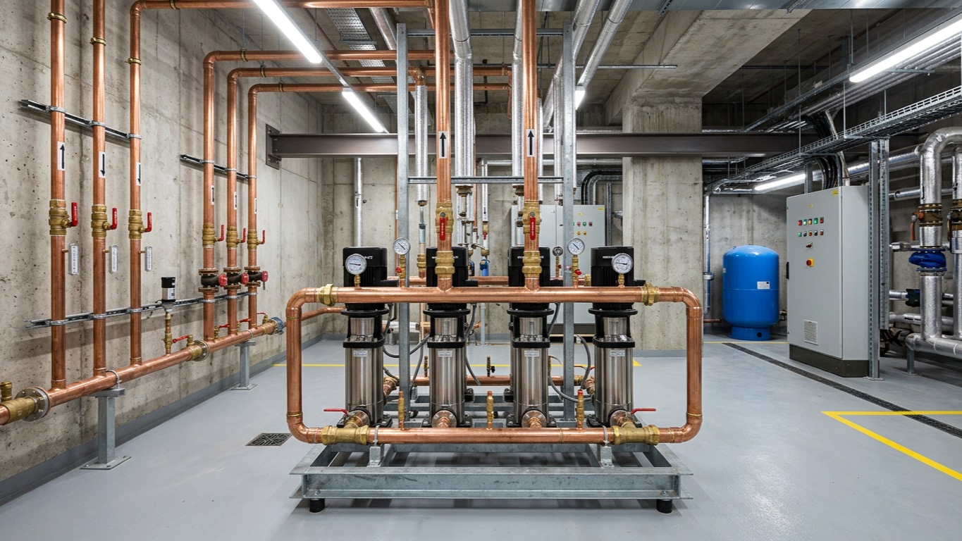
Booster Sets and Variable Speed Control
Modern high-rise pumping systems increasingly favour variable-speed booster sets over fixed-speed pumps with bypass control. These systems adjust pump speed in response to system demand, maintaining target pressure at a reference point whilst minimising energy consumption.
A typical booster set comprises two or three pumps operating in parallel, each fitted with variable frequency drives (VFDs). Control algorithms sequence pumps based on demand, running one unit at partial speed during low loads and bringing additional pumps online as flow requirements increase.
For central heating equipment in tall buildings, variable speed control delivers substantial energy savings - often 30-50% compared to fixed-speed arrangements - because pump power consumption varies with the cube of speed. Reducing speed by 20% cuts power consumption by nearly 50%.
Pressure sensors installed at critical points - typically the highest or most hydraulically remote location in each zone - provide feedback to the control system. The VFD adjusts speed to maintain setpoint pressure regardless of varying flow demands as terminal units modulate or switch on and off.
Booster set configurations must consider redundancy requirements. An N+1 arrangement provides standby capacity, ensuring full system operation continues if one pump requires maintenance. Critical applications may specify N+2 redundancy or duty-assist-standby configurations where the standby pump can provide partial backup capacity.
Pump Specifications for Different Zone Applications
Lower zones in high-rise buildings demand robust pumps capable of handling high pressures and potential cavitation risks. These installations typically specify end-suction or inline pumps with heavy-duty mechanical seals rated for continuous operation at 10-16 bar.
Cast iron construction suffices for most heating applications, though stainless steel pumps offer advantages in cooling systems or where water quality concerns exist. Motor sizing must account for the full head requirement including static pressure, typically ranging from 45-90 metres total head for lower-zone duties.
Middle zones present more moderate conditions, with total head requirements typically falling between 25-45 metres. Lowara pumps designed for commercial building services offer suitable performance characteristics for these applications, combining efficient operation with reliable construction.
Upper zones allow more compact, energy-efficient pump selections. Total head requirements often fall below 25 metres, permitting smaller motors and reduced electrical infrastructure. High-efficiency circulators with permanent magnet motors deliver excellent performance in these applications, particularly when paired with variable speed control.
All zones require careful attention to expansion vessel sizing, air elimination, and system protection. Each zone operates as an independent pressurised system requiring proper commissioning and pressure testing before handover.
Control Integration and Building Management Systems
Sophisticated control strategies optimise pump performance across multiple pressure zones whilst integrating with broader building management systems (BMS). National Pumps and Boilers supplies modern installations that communicate via BACnet, Modbus, or proprietary protocols, allowing centralised monitoring and adjustment.
Each zone's pump controller monitors key parameters: flow rate, differential pressure, motor current, operating hours, and alarm conditions. This data feeds into the BMS, enabling facility managers to identify efficiency opportunities, predict maintenance requirements, and respond quickly to developing issues.
Pressure setpoint optimisation represents a significant efficiency opportunity. Rather than maintaining fixed pressure targets, adaptive control algorithms adjust setpoints based on actual demand signals from terminal units. If all zone valves operate well below full open position, the system incrementally reduces pressure until at least one valve approaches full open, ensuring adequate pressure whilst eliminating waste.
Lead-lag rotation extends pump life by distributing operating hours evenly across multiple units. The control system automatically rotates which pump serves as lead, preventing one unit from accumulating disproportionate wear whilst others remain idle.
Fault detection algorithms monitor performance trends to identify degrading conditions before failures occur. Declining efficiency, increasing vibration, or rising motor current trigger maintenance alerts, allowing planned interventions rather than emergency repairs.
Energy Efficiency Considerations Across Zones
Pump selection high rise buildings significantly impacts long-term energy costs. Pumping systems in large commercial buildings typically consume 10-20% of total electrical load, making efficiency improvements financially attractive.
Variable speed drives represent the most impactful efficiency measure, but proper sizing remains equally important. Oversized pumps operate inefficiently at partial loads, whilst undersized units run continuously at maximum speed, sacrificing control range and increasing wear.
Each zone should include separate energy metering to establish baseline consumption and track improvement initiatives. Comparing energy use per square metre or per degree-day across zones helps identify underperforming systems requiring attention.
Hydraulic optimisation reduces pumping energy by minimising circuit resistance. Properly sized pipework, low-resistance valves, and efficient heat exchangers allow lower pump heads and reduced energy consumption. A 10-metre reduction in system head can cut pumping energy by 20-30% depending on the pump curve characteristics.
DHW pumps serving high-rise domestic hot water systems benefit from similar zoning strategies, though the intermittent demand profile creates different control challenges compared to space heating applications.
Commissioning and Performance Verification
Proper commissioning ensures each pressure zone delivers design performance whilst operating efficiently. The process begins with pre-commissioning checks: verifying electrical connections, confirming rotation direction, checking valve positions, and testing control sequences without water flow.
Static pressure testing confirms system integrity before filling and pressurising. Each zone undergoes separate testing to its design pressure plus a safety margin, typically 1.5 times working pressure, held for a minimum period to verify leak-tightness.
Flow balancing establishes correct distribution across branches and terminal units. Commissioning engineers measure flow rates at key points, adjusting balancing valves to achieve design conditions. This process works from the extremities inward, ensuring the most hydraulically remote points receive adequate flow before adjusting closer locations.
Pump performance verification compares measured head and flow against the manufacturer's curves. Portable ultrasonic flow meters and differential pressure gauges allow non-invasive testing. Significant deviations from expected performance indicate sizing errors, installation problems, or defective equipment requiring investigation.
Control system proving exercises all sequences: lead-lag changeover, alarm responses, BMS communication, and setpoint adjustment. Each zone's controls must respond appropriately to simulated and actual demand variations.
Maintenance Planning for Multi-Zone Systems
High-rise pumping systems require structured maintenance programmes addressing each zone independently whilst considering system-wide interactions. Routine inspections should occur quarterly, examining pumps, valves, expansion vessels, and control equipment for signs of wear or developing problems.
Annual maintenance typically includes bearing lubrication (for pumps without sealed bearings), mechanical seal inspection, coupling alignment checks, and motor insulation testing. Variable frequency drives require periodic inspection of cooling fans, capacitors, and electrical connections.
Five-year overhauls involve more extensive work: mechanical seal replacement, bearing renewal, impeller inspection, and motor rewinding if condition assessment indicates declining insulation resistance. Planning these interventions across zones prevents simultaneous outages affecting building comfort.
Spare parts inventory should include critical components for each pump type installed: mechanical seals, bearings, coupling elements, and impellers. For buildings with multiple identical pumps, maintaining one complete spare pump assembly allows rapid replacement during failures, minimising downtime whilst repairs proceed offline.
Water quality monitoring prevents long-term degradation. Regular testing for pH, dissolved oxygen, and contamination helps identify treatment system failures before they cause pump damage. Strainer inspection reveals debris accumulation indicating corrosion or installation residue requiring system flushing.
Conclusion
Effective pressure zoning transforms high-rise building services from hydraulic challenges into efficient, reliable systems. By dividing vertical structures into manageable zones, each served by appropriately specified pumping equipment, building services engineers deliver consistent performance whilst protecting components from excessive pressure and optimising energy consumption.
Success requires careful calculation of zone boundaries, accurate pump duty point determination, and thoughtful selection between PRV-based or break tank separation strategies. Variable speed booster sets with intelligent controls offer superior efficiency and comfort compared to traditional fixed-speed arrangements, though they demand more sophisticated commissioning and maintenance approaches.
The long-term performance of multi-zone systems depends on proper specification, installation quality, and ongoing maintenance. Buildings benefit from energy metering at each zone, enabling performance tracking and efficiency improvement initiatives. Regular inspection and planned maintenance prevent unexpected failures whilst extending equipment life.
For technical guidance on pump selection high rise buildings or pressure zoning strategies specific to particular building requirements, contact us for expert support tailored to commercial building services applications.