
Submersible Pumps for Basement Drainage: A Selection and Installation Guide
Basements occupy the most vulnerable position in any UK building from a water ingress perspective. Below ground level on all sides, with no possibility of gravity drainage to the sewer, a basement depends on submersible pump basement drainage systems to remove the groundwater, surface water, and incidental water that would otherwise accumulate and cause structural damage, mould growth, and loss of use of potentially significant floor space. Getting the pump system specification right determines whether a basement functions reliably for decades or becomes a persistent problem that damages property and erodes building value.
The UK's variable water table, predominantly clay and impermeable soils in many regions, and increasing frequency of intense rainfall events make submersible pump basement drainage systems a non-optional component of usable below-grade space rather than a precautionary extra. A basement without a properly specified and maintained pump system is not a waterproofed basement - it is a basement with waterproofing that has not yet been tested to failure.
Why Basements Need Dedicated Drainage Pumps
The fundamental constraint of below-ground drainage is that water cannot flow uphill to reach the sewer connection. In the vast majority of UK buildings, the main sewer connection sits above basement floor level, making gravity drainage to the external drainage system physically impossible regardless of how the internal drainage is arranged. Every drop of water that enters a basement through groundwater ingress, surface flooding, or pipe leakage must be lifted mechanically to reach the drainage system - a role that only a submersible pump basement drainage system can fulfil reliably in permanent installations.
Groundwater ingress routes into basements are numerous and often difficult to seal completely. Wall-to-floor joints in reinforced concrete construction allow water movement under hydrostatic pressure when the water table rises above floor level. Structural cracks in concrete walls and slabs develop over time as the building settles and temperature cycling creates micro-movement. Even purpose-applied waterproofing membranes develop pinholes and localised failures that allow seepage into the basement void. Rather than relying on a single membrane layer to be completely watertight indefinitely, the BS 8102 approach to basement waterproofing incorporates drainage channels directing water to a sump where a submersible drainage pump removes it - accepting that some water will enter and managing it before damage occurs.
The consequences of inadequate basement drainage compound rapidly once water accumulates. Structural concrete and masonry suffers accelerated deterioration from repeated wetting and drying cycles that carry soluble salts to the surface. Mould growth on internal finishes begins within 48–72 hours of persistent dampness. Building contents, electrical installations, and mechanical equipment suffer damage that insurance may not cover if the drainage system provided was inadequate for the known water ingress risk.
Sources of Basement Water Requiring Pump Removal
Groundwater Ingress
Groundwater ingress occurs when the local water table rises seasonally above the basement floor slab level. In clay-rich soils typical of much of urban UK, the water table can rise by 1–3 metres between summer and winter as rainfall saturates the poorly draining soil profile. A basement that remains dry through summer may face significant hydrostatic pressure against its walls and floor throughout the winter months, pushing water through any weakness in the construction.
Seasonal groundwater ingress creates predictable submersible pump basement drainage demand concentrated in the October to March period, with peak demand during prolonged wet weather. Understanding this seasonal pattern allows correct pump sizing: the peak inflow rate during the worst seasonal conditions determines the required pump capacity, not the average inflow across the year. For Grundfos submersible drainage pump selection in high water table locations, the technical guidance includes groundwater ingress estimation methodologies based on soil permeability and hydrostatic head that provide a quantified basis for pump sizing rather than rule-of-thumb estimates.
Surface Water and Flooding
Surface water enters basements through drainage system surcharge during heavy rainfall events that exceed the sewer system's capacity. When the external sewer surcharges, water backs up through the building's drainage connections and emerges from the lowest floor gullies or WC pans - directly into the basement. A non-return valve on the building's drainage connection to the sewer prevents this backflow, but many older UK buildings lack this protection.
Flash flooding from intense localised rainfall - increasingly common under UK climate projections - overwhelms surface drainage and enters basements through light wells, below-grade windows, and doors at basement level. These entry routes bring large volumes of water in short periods, requiring submersible pump basement drainage capacity sized for peak flood event flow rates that may be 10–20 times the normal groundwater ingress rate. The pump system that handles routine groundwater may be wholly inadequate for a flash flood scenario, making dual pump systems the prudent specification in high flood risk locations.
Condensation and Incidental Water
Mechanical equipment in basement plant rooms generates condensate and incidental water that must drain from spaces where floor gullies and gravity drainage connections are not provided. Boiler condensate neutralisation units discharge periodically. Water heater safety valve drain pipes must terminate safely. Washing machines and utility sinks in basement utility rooms require drainage that runs uphill to reach any available gravity connection.
For DHW pumps and heating system drainage in basement plant rooms, the submersible pump sump may serve a dual function: draining both mechanical equipment condensate and incidental leakage from pipework connections alongside the primary groundwater management role. This dual function must be accounted for in both sump sizing and pump capacity, as the combined flow from all sources determines the required system specification.
Sump Pit Design for Basement Drainage
Sizing the Sump Pit
The sump pit must hold sufficient volume between the pump activation level (float switch high) and the pump cutoff level (float switch low) to prevent rapid cycling. Each pump start and stop constitutes one cycle, and motor manufacturers specify maximum starts per hour - typically 10–20 for domestic pump motors and 5–10 for larger commercial motors. Exceeding this limit overheats the motor windings during the repeated start inrush current events and shortens motor life proportionally to the cycling excess.
A minimum pit volume of 50 litres between activation and cutoff levels suits most domestic submersible pump basement drainage applications with typical groundwater inflow rates. This provides adequate buffer time between pump cycles even when inflow rate is high relative to the pump's flow rate. For commercial basement applications with larger pumps and higher inflow rates, the minimum volume between levels increases proportionally - the pit must be sized to the pump and inflow combination, not specified generically.
Sump Pit Construction
Precast concrete rings forming a cylindrical sump pit are the standard construction method in new basement floors, with ring diameters of 450mm to 1,000mm available depending on the pump size and required volume. The pit base must be permeable - either open to the subgrade or fitted with aggregate - to allow groundwater to enter freely. A sealed concrete base defeats the purpose of providing a collection point for groundwater ingress.
For occupied basements, a sealed lid over the sump pit prevents odour transmission, reduces humidity from evaporation, and maintains a clean environment. The lid must be removable for pump access and maintenance without requiring specialist tools, and must not create a confined space classification issue that would make routine maintenance impractical for building management staff. DAB submersible drainage pumps with low-profile designs fit within compact precast sump rings whilst maintaining adequate flow rates for domestic and light commercial basement applications.
Selecting a Submersible Pump for Basement Drainage
Flow Rate and Head Requirements
Calculating the required pump flow rate starts with estimating peak inflow - the maximum rate at which water enters the sump under the worst expected conditions. For groundwater ingress applications, specialist geotechnical assessment can provide quantified inflow rates based on soil permeability and hydrostatic head. In the absence of site-specific data, conservative estimates based on construction type and local geology provide a starting point that over-sizes rather than under-sizes the pump.
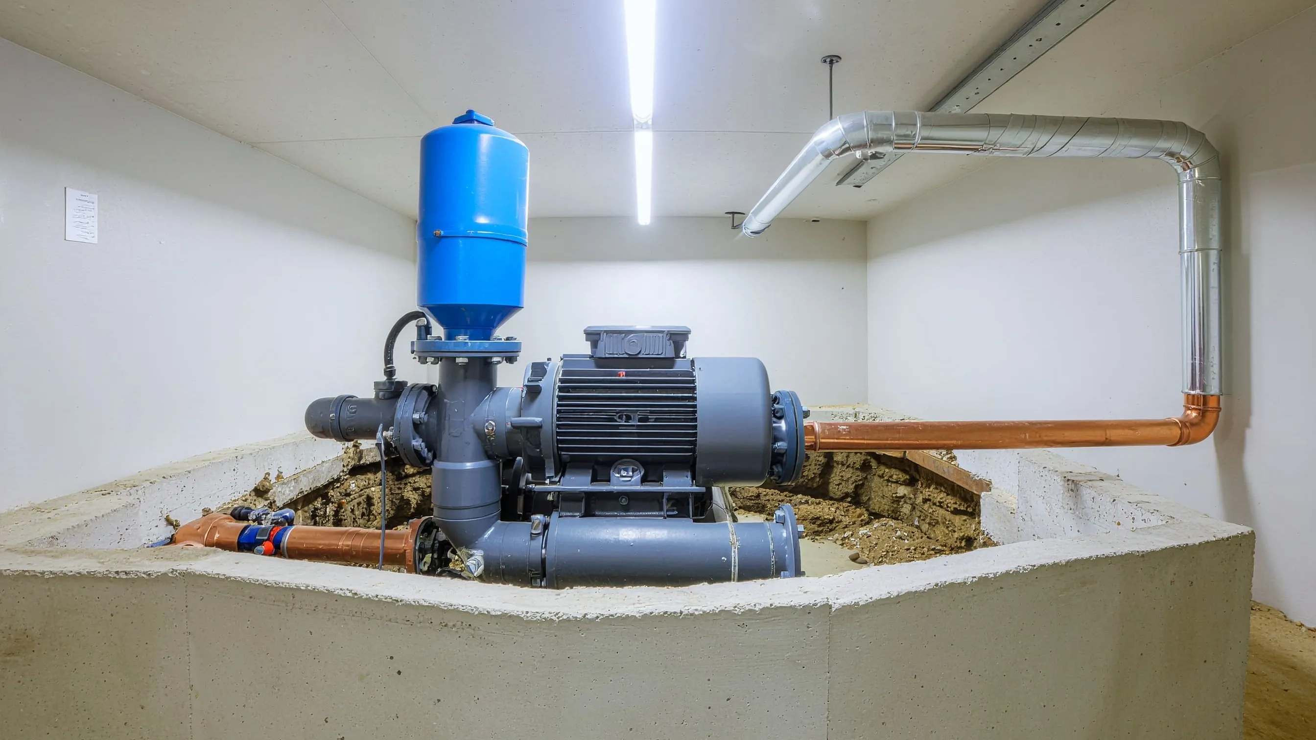
Total head calculation adds the vertical lift from sump base to the discharge point to the friction losses in the discharge pipework. For a basement with 2 metres of vertical lift to the discharge connection and 15 metres of 40mm pipework, total head might reach 3.5–4 metres including minor losses at bends and the non-return valve. The selected pump must deliver adequate flow at this total head, not just at zero head - a pump rated at 10 litres per minute at zero head may deliver only 4 litres per minute against 4 metres of head. Wilo submersible drainage pump performance curves show flow against head across the operating range, enabling correct duty point selection for each specific installation rather than relying on headline flow rate figures that apply only at near-zero head.
Pump Construction for Basement Applications
Stainless steel construction for the pump casing and impeller provides corrosion resistance in the variable water chemistry typical of UK groundwater, which may carry dissolved iron, calcium, or aggressive dissolved gases depending on the local geology. Cast iron components suit applications where water chemistry is known to be compatible and pump economics favour the lower initial cost. For domestic basement installations where long-term corrosion resistance matters more than initial purchase price, stainless steel submersible drainage pumps provide reliable service with minimal maintenance attention.
Integrated float switches within the pump body simplify installation in compact sump pits where a separate float on a cable would occupy the limited space available. However, external float switches provide independent adjustment of activation and cutoff levels without removing the pump, which is advantageous when the inflow rate requires fine-tuning of the operational levels to optimise cycling frequency. For Lowara submersible drainage pump installations where precise level control between activation and cutoff levels affects cycling frequency in pumps serving sumps with limited storage volume, the external float switch arrangement provides the flexibility that integrated floats cannot.
Automatic Operation Requirements
Automatic operation is the non-negotiable requirement for submersible pump basement drainage systems in occupied buildings. A pump that requires manual activation to manage groundwater ingress fails its primary purpose - groundwater enters continuously regardless of whether the building is occupied, and a basement flooded during a weekend absence or overnight creates damage that hours of automatic pumping would have prevented for a cost of pence in electricity.
Battery backup provision becomes significant in flood scenarios where mains power failure coincides with the flooding event - precisely the circumstances when drainage is most critical. A battery backup module maintaining pump operation for 6–12 hours during power outages is a modest additional cost in the context of the damage a flooded basement can cause during that period.
Dual Pump Systems for Critical Basement Protection
Duty/standby pump arrangements provide the operational redundancy that critical basement applications require. The duty pump handles normal groundwater management on automatic float switch control. The standby pump activates automatically when the water level rises to a higher setpoint, indicating the duty pump has failed or is operating but cannot keep pace with inflow. A high-level alarm notification at a further elevated setpoint alerts the building manager that the standby pump is operating and the duty pump requires attention.
For National Pumps and Boilers commercial basement drainage installations serving occupied premises where flooding would disrupt operations, dual pump systems with independent power circuits provide the reliability that single-pump systems cannot match. Placing each pump on a separate electrical circuit ensures that a circuit breaker trip or wiring fault affecting one pump does not simultaneously take the standby offline - a common failure mode in dual pump systems where both pumps share a single supply circuit.
Discharge Pipework Design
Discharge pipework must be sized to carry the pump's flow rate without creating excessive friction losses that reduce effective head and therefore flow rate at the duty point. Minimum 40mm pipework suits domestic submersible pump basement drainage applications with pumps up to 0.5 kW. Commercial applications with larger pump flow rates require 50mm or 63mm pipework to keep friction losses within acceptable limits.
A non-return valve on the discharge pipework is mandatory. Without it, water in the discharge pipe flows back into the sump when the pump stops, refilling part of the pit volume and activating the pump again almost immediately - creating rapid cycling that exceeds motor start frequency limits. The non-return valve must be rated for the pump's working pressure and sized for the pipework diameter. Pump valves including non-return valves suitable for submersible pump discharge connections are available in all standard pipework sizes, with check valves that provide low-resistance flow in the pumping direction and positive seating when flow reverses.
Regulations and Compliance
Building Regulations Approved Document H governs drainage from buildings including pumped discharge systems for basements. Discharge from ground-level or above-ground drainage may connect to the surface water sewer or soakaway, whilst discharge from below-ground spaces containing sanitary facilities must connect to the foul sewer. The distinction matters for connection approval and the pump specification must reflect the correct discharge destination.
BS EN 12050 applies to sewage lifting stations serving below-ground sanitary facilities - toilets, showers, and sinks discharging to a pumped system rather than gravity drainage. This standard specifies minimum tank volumes, pump redundancy requirements, alarm provisions, and access arrangements that commercial basement toilet installations must meet. A submersible drainage pump system serving a below-ground toilet facility that does not comply with BS EN 12050 fails Building Control approval regardless of pump performance.
Maintenance Requirements for Basement Drainage Pumps
Monthly manual activation tests confirm the pump starts and clears water as expected. This test involves either manually operating the float switch or introducing water to raise the sump level to the activation point, then observing that the pump activates, moves water visibly through the discharge pipe, and stops when the level falls to the cutoff point. A pump that starts and runs but does not visibly reduce sump level indicates a discharge problem - non-return valve failure, blocked discharge pipework, or a pump delivering insufficient flow against the actual head.
Annual inspection involves removing the pump from the sump, inspecting the impeller for wear or debris accumulation, checking the float switch mechanism for free movement and correct activation points, and cleaning any sediment from the pit base that could accumulate to obstruct pump operation. Recording the pump's performance during annual inspection provides the trend data that identifies degrading performance before failure occurs.
Common Faults and Their Causes
A pump that starts but fails to reduce the pit level despite running continuously indicates either discharge restriction from a blocked non-return valve or collapsed pipework, or a pump whose flow rate is insufficient for the actual inflow rate at that head. Distinguishing between these causes requires checking whether the discharge pipe shows flow at the outlet point - no flow confirms a discharge restriction, whilst flow at the outlet with a rising pit level confirms inflow exceeds pump capacity.
A pump that does not start when the water reaches the activation level indicates either a float switch fault - the most common cause in domestic applications where the float can become entangled with the pump body or accumulated debris - or an electrical supply fault. Testing the float switch by manually lifting it to the activation position confirms whether the pump motor is functioning and the supply is available, with inactivity on manual float operation pointing to an electrical fault rather than the float mechanism.
Conclusion
Effective submersible pump basement drainage protects both the structural integrity of below-grade construction and the usability of basement spaces throughout the UK's wet climate. Correct sump pit sizing, appropriate pump selection for the specific inflow rates and head requirements, non-return valve provision on discharge pipework, automatic operation with battery backup, and regular maintenance combine to create a drainage system that manages groundwater ingress and flooding events reliably for decades.
For guidance on designing or upgrading submersible pump basement drainage systems for specific buildings, flood risk assessments, or compliance with Building Regulations Part H and BS EN 12050, Contact Us to discuss your basement drainage requirements with engineers experienced in both the hydraulic design and regulatory compliance aspects of below-ground drainage systems.