
The Importance of Isolation Valves in Pump Systems: Where and Why
Pump systems fail more often from poor isolation than from pump defects. A blocked impeller, a leaking seal, or routine maintenance becomes a system-wide shutdown when isolation valves are missing or incorrectly positioned. For heating engineers and mechanical contractors working with commercial HVAC systems, understanding isolation valve placement prevents costly downtime and protects system integrity.
National Pumps and Boilers supplies isolation valve configurations for pump systems ranging from small domestic circulators to large commercial installations. The difference between a 20-minute pump swap and a full system drain often comes down to valve placement decisions made during initial installation.
What Isolation Valves Actually Do in Pump Systems
Pump isolation valves create serviceable sections within a hydraulic system. They allow technicians to isolate a pump for maintenance, replacement, or inspection without draining the entire system or shutting down connected equipment. In a commercial building with multiple heating zones, proper isolation means servicing a failed pump on the third floor without affecting ground-floor operations.
The valve creates a physical barrier that stops flow and holds system pressure on one side while the isolated section is depressurised and worked on. This function becomes critical in systems containing glycol mixtures, treated water, or pressurised circuits where refilling and recommissioning carry significant cost and complexity.
Three Primary Valve Types for Pump Isolation
Three valve types dominate pump isolation applications:
Gate valves provide full-bore flow with minimal pressure drop when fully open. They suit larger commercial systems where flow restriction affects pump performance. Gate valves work best for isolation purposes rather than flow control - they operate fully open or fully closed.
Ball valves offer quick quarter-turn operation and reliable sealing. The spherical closure element provides a tight shut-off with minimal maintenance. Ball valves handle higher pressures than gate valves of equivalent size and suit most commercial heating applications.
Butterfly valves reduce installation space and cost in larger pipe sizes above 65mm. The disc-style closure rotates 90 degrees to open or close. Butterfly valves introduce slightly more pressure drop than gate or ball valves but prove economical for commercial boiler rooms and district heating systems.
Critical Isolation Points in Pump Installations
Pump Inlet and Outlet Isolation
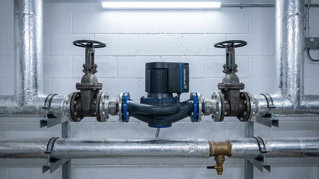
Every pump requires pump isolation valves on both the suction (inlet) and discharge (outlet) sides. This configuration creates a serviceable pump section that can be drained independently. Without both valves, removing the pump requires draining back to the nearest isolation point - potentially hundreds of litres in commercial systems.
The inlet valve must be fully open during operation to prevent cavitation. Partially closed inlet valves create low-pressure zones that cause vapour bubbles to form and collapse against the impeller, causing noise, vibration, and mechanical damage. Systems using Grundfos pumps or Wilo circulators specify minimum inlet pressures to prevent cavitation - inlet isolation valves must not restrict flow when operational.
The outlet valve controls discharge pressure and can be partially closed for commissioning or flow balancing, though dedicated balancing valves suit this purpose better. During pump maintenance, the outlet valve prevents backflow through the pump from system pressure on the discharge side.
Valve sizing matches pipe diameter at the pump connection. Undersized valves create unnecessary pressure drops that force the pump to work harder, increasing energy consumption and reducing service life. A 50mm pump connection requires 50mm isolation valves - reducing to 40mm valves to save cost creates a restriction that affects pump performance curve.
Bypass Line Isolation
Pump systems serving critical applications require bypass configurations that allow flow to continue during pump maintenance. The bypass line runs parallel to the pump with its own isolation valve. During normal operation, the bypass valve remains closed and the pump circulates flow. For pump maintenance, technicians close the pump inlet and outlet valves, open the bypass valve, and maintain system circulation through the bypass line.
Bypass arrangements suit systems where flow interruption causes problems: domestic hot water circulation, process cooling, or critical heating zones. The bypass line diameter typically matches the pump outlet size to maintain adequate flow rates during bypass operation.
Some commercial installations use duty/standby pump pairs instead of bypass lines. Each pump has complete isolation valve sets, and only one pump operates at a time. If the duty pump fails, the standby pump starts while the failed unit receives maintenance. This configuration provides redundancy beyond simple bypass arrangements and suits larger commercial buildings or industrial processes.
Check Valve Integration
Non-return valves (check valves) prevent reverse flow through pumps when they stop. In systems with multiple pumps or significant static head, check valves protect against backflow that can cause pump rotation in reverse - potentially damaging mechanical seals and bearings.
The check valve installs on the pump discharge side between the pump and the outlet isolation valve. This isolation valve placement allows the check valve to be serviced along with the pump when both isolation valves close. Installing the check valve downstream of the outlet isolation valve means it cannot be accessed during pump maintenance without additional system isolation.
Spring-loaded check valves suit horizontal pipe runs and provide positive closure regardless of flow velocity. Swing check valves work in horizontal or vertical upward flow and rely on gravity for closure. The valve type selection depends on pipe orientation, flow velocity, and closing speed requirements.
Systems using variable-speed pumps may experience check valve chatter - the valve rapidly opens and closes as flow fluctuates. This creates noise and mechanical wear. Selecting check valves with appropriate spring rates or dampening mechanisms prevents chatter in variable-flow applications common with modern ErP-compliant circulators.
Drain and Vent Points
Isolated pump sections require drain valves at low points and vent valves at high points. Without proper drainage, removing a pump still requires dealing with trapped water in the isolated section. A 50mm pump with inlet and outlet isolation typically contains 2-3 litres of water that drains across the floor during removal unless proper drain points exist.
Drain valves should be 15mm or 20mm gate or ball valves positioned at the lowest point in the isolated section. In horizontal pump installations, this means a drain point on the pump body or inlet pipework. A short length of hose connects to the drain valve to direct water into a bucket or floor drain during pump removal.
Vent valves release trapped air when refilling the isolated section after maintenance. Air pockets prevent proper pump priming and cause noise and vibration during startup. Manual vent valves are installed at the highest point in the isolated section - typically on the pump volute or discharge pipework. Automatic air vents suit systems where manual venting proves impractical, though they require their own isolation valves for servicing.
System-Specific Valve Requirements
Central Heating Pump Isolation
Domestic and light commercial central heating pumps using circulators up to 32mm connections typically employ ball valves with integral unions. These valve sets combine isolation and union functions in a compact assembly that allows pump removal by loosening the union nuts without disturbing pipework.
The valve bodies remain permanently installed in the system pipework. During pump replacement, the union nuts unscrew to release the pump, which withdraws from between the valve bodies. This configuration suits space-constrained boiler rooms and allows pump replacement without pipe cutting or soldering.
Valve sets must match pump connection types. Grundfos UPS series pumps use proprietary union connections that require compatible valve sets. Generic valve sets may not seal correctly or may require adapters that introduce additional leak points.
DHW Circulation Valve Placement
DHW pumps circulate hot water through secondary return systems to maintain instant hot water at outlets. These systems operate continuously or on timers, and pump failures cause complaints about slow hot water delivery.
DHW circulation pumps require the same inlet/outlet isolation as heating circulators, but bronze or stainless steel valve construction suits the higher water quality and temperature cycling. Brass valves in DHW systems can dezincify over time, particularly in soft water areas, leading to valve failure and contamination.
The pump typically installs on the return line before it reconnects to the cylinder or calorifier. Proper isolation valve placement allows pump replacement without draining the entire DHW system or interrupting hot water supply to the building. Check valves prevent gravity circulation when the pump stops, which would waste energy and affect temperature control.
Commercial Boiler Pump Configurations
Commercial heating systems using multiple boilers require careful valve placement to allow individual boiler or pump isolation without affecting operational equipment. Header systems with multiple boilers feeding common flow and return headers need isolation valves on each boiler's flow and return connections plus isolation for each pump.
This arrangement allows a single boiler to be taken offline for maintenance while others continue operating. The pump serving the isolated boiler must have its own isolation valve set to prevent flow through the stopped pump from operating boilers.
Large commercial systems often specify Lowara pumps or DAB pumps for their robust construction and commercial duty ratings. These pumps may have flanged connections rather than threaded unions, requiring flanged isolation valves with appropriate pressure ratings for the system design conditions.
Pressurisation Unit Valve Integration
Sealed heating systems use pressurisation units containing expansion vessels and pressure controls. The connection between the pressurisation unit and the system requires isolation to allow vessel replacement or pressure testing without draining the entire system.
The isolation valve installs on the cold feed connection between the pressurisation unit and the system. This valve remains fully open during operation and closes only for pressurisation unit maintenance. Some engineers incorrectly install the isolation valve between the expansion vessel and the pressurisation unit manifold, which prevents proper pressure cushioning and can cause vessel failure.
Systems using automatic filling units require additional isolation on the mains water supply connection. This allows filling unit maintenance without shutting off building water supplies. The isolation valve must be a full-bore type that doesn't restrict flow during system filling operations.
Installation Practices That Affect Valve Performance
Valve Orientation and Accessibility
Ball valves and gate valves function in any orientation, but the handle position affects accessibility. Installing valves with handles pointing toward walls or other equipment makes operation difficult during emergencies. Valve handles should point toward accessible areas with sufficient clearance for operation - typically 150mm minimum for quarter-turn ball valves.
Butterfly valves in larger systems require clearance for the lever handle to rotate 90 degrees. The handle arc must not intersect with adjacent pipework, cable trays, or structural elements. Planning valve orientation during design prevents installation conflicts that force awkward handle positions or require expensive pipe modifications.
Labelling valves clearly prevents confusion during maintenance. A boiler room with 20 unlabelled isolation valves becomes a puzzle during emergency shutdowns. Engraved laminate labels zip-tied to valve handles identify function and system served. Labels should state "Pump 1 Inlet", "Pump 2 Outlet", "Bypass Valve" rather than vague descriptions.
Valve Quality and Specification
Cheap pump isolation valves fail more frequently and cost more in the long term than quality components. A £15 ball valve that seeps after two years requires system drainage, valve replacement, and refilling - easily £200 in labour and materials. A £35 quality valve from established manufacturers provides reliable service for decades.
Valve specifications must match system conditions. A heating system operating at 2 bar and 80°C requires valves rated for these conditions with appropriate safety margins. Using domestic plumbing valves rated for cold water in heating applications leads to premature failure as seals degrade and bodies distort under thermal cycling.
Material compatibility matters in systems containing glycol antifreeze or corrosion inhibitors. Standard EPDM seals suit most heating applications, but glycol concentrations above 30% may require Viton seals for extended service life. Valve manufacturers specify seal materials compatible with different fluids - checking compatibility during specification prevents seal degradation and leakage.
Commissioning and Testing Procedures
Initial Valve Testing and Verification
New installations require valve testing before the system enters service. Each isolation valve should be operated through its full range to verify smooth operation and proper seating. Stiff or binding valves indicate installation stress, misalignment, or manufacturing defects that will worsen over time.
Pressure testing the system with isolation valves in various positions confirms that closed valves hold pressure and open valves allow flow. A valve that weeps under test pressure will leak during operation. Identifying defective valves during commissioning allows replacement before the system becomes operational and downtime becomes costly.
Documentation should record valve locations, types, and sizes in system commissioning records. This information proves invaluable during future maintenance when the original installation team may not be available. Updating valve schedules when modifications occur maintains accuracy for future work.
Maintenance and Long-Term Reliability
Preventing Valve Seizure Through Regular Operation
Isolation valves require periodic operation to prevent seizure. Valves that remain in one position for years can become stuck as scale deposits or corrosion products bind moving parts. An annual maintenance schedule should include operating each isolation valve through its full range and returning it to the normal position.
Gate valves particularly suffer from stem seizure when left undisturbed. The threaded stem can corrode to the body, making the valve impossible to operate without destructive removal. Operating gate valves annually and applying appropriate lubricants to exposed stems prevents seizure and extends service life.
Ball valves prove more reliable than gate valves for long-term isolation duty. The spherical ball and simple quarter-turn operation resist seizure better than threaded gate valve stems. For critical isolation points, ball valves justify their higher initial cost through superior long-term reliability.
Addressing Valve Leaks and Gland Issues
Leaking valve glands can often be resolved by tightening the packing nut rather than replacing the entire valve. Gate valves and some ball valves have adjustable gland packing that can be compressed to stop stem leaks. Over-tightening makes valve operation stiff and damages packing, so adjustment requires care and experience.
Conclusion
Isolation valve placement determines whether pump maintenance takes 30 minutes or requires a full system shutdown. Every pump needs inlet and outlet isolation as a minimum. Critical systems require bypass arrangements or duty/standby configurations. Check valves prevent reverse flow damage, while drain and vent points allow proper isolated section servicing.
Valve quality matters more than initial cost. Properly specified and installed pump isolation valves from manufacturers provide decades of reliable service. Cheap alternatives fail prematurely and cost more in labour and downtime than any initial savings justify.
System designers and installers who understand isolation valve placement requirements create maintainable systems that minimise operational disruption. The extra valves and fittings add modest cost during installation but deliver substantial value over the system's service life.
National Pumps and Boilers stocks a comprehensive range of pump valves and pump equipment for commercial and domestic applications. For specific advice on isolation valve configurations for your project, contact us for support based on real UK installation experience across commercial HVAC and building services applications.