
The Role of Pressure Gauges in Spotting Pump System Issues
Pressure gauges often sit unnoticed on pump systems until something goes wrong. Yet these simple instruments provide the earliest warning signs of developing faults, long before catastrophic failures occur. A gauge reading that deviates from normal operating parameters signals underlying issues with pump performance, system integrity, or component wear that require immediate attention.
For heating engineers and pump specialists, understanding how to interpret pressure gauge readings transforms routine inspections into predictive maintenance opportunities. The difference between catching a worn impeller early and replacing an entire pump assembly often comes down to recognising subtle pressure changes. Effective pressure gauge pump issues identification prevents costly emergency repairs.
Why Pressure Monitoring Matters in Pump Systems
Pump systems operate within specific pressure parameters determined by system design, pipe sizing, and component specifications. When pressure readings fall outside these parameters, the pump works harder to maintain flow, consuming more energy and accelerating component wear.
A central heating system designed to operate at 1.5 bar that consistently shows 0.8 bar indicates a problem, whether that is a leak, faulty expansion vessel, or air ingress. Similarly, a commercial circulator showing discharge pressure 20% below specification suggests impeller wear, blockage, or cavitation issues.
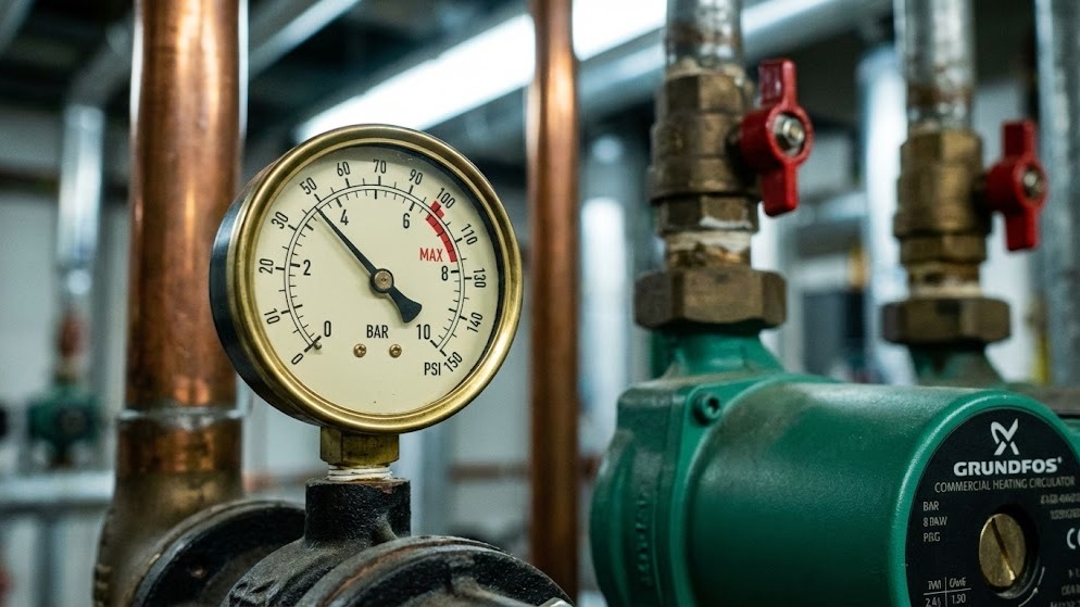
The financial impact proves significant. Research from the Hydraulic Institute found that pumps operating outside optimal pressure ranges consume 15-30% more energy whilst delivering reduced performance. For a commercial building running multiple Grundfos pumps continuously, this translates to thousands in unnecessary annual costs.
Pressure gauges provide real-time feedback on system health without requiring specialist diagnostic equipment. A £15 gauge can prevent a £1,500 pump replacement by identifying issues during their early stages. Manometer diagnostics heating applications rely on these fundamental measurement principles.
Common Pressure Gauge Readings and What They Indicate
Low Suction Pressure
Suction pressure below normal operating parameters typically indicates problems on the inlet side of the pump. Common causes include:
Blocked strainer or filter represents the most frequent culprit in domestic heating systems. A clogged filter creates resistance that reduces suction pressure by 0.2-0.5 bar. Regular filter inspection prevents this issue, yet many installations lack adequate maintenance schedules.
Air leaks on suction side occur even with small leaks in pipe joints or valve glands, allowing air ingress that reduces suction pressure whilst introducing air into the system. This creates noise, reduces efficiency, and accelerates corrosion.
Cavitation happens when suction pressure drops below the liquid's vapour pressure, causing bubbles to form and collapse violently against the impeller. This produces characteristic rattling sounds and causes rapid component damage. Cavitation typically occurs when net positive suction head (NPSH) requirements are not met.
Closed or partially closed isolation valve from human error accounts for many pressure issues. A valve left partially closed after maintenance creates unnecessary resistance. Pressure gauge pump issues often trace back to these simple causes.
High Discharge Pressure
Elevated pressure on the discharge side indicates increased system resistance or flow restrictions:
Closed or throttled discharge valve creates backpressure that forces the pump to work against increased head. This reduces flow rate and increases power consumption.
Blockage in system pipework from debris, scale buildup, or magnetite accumulation in heating systems restricts flow and elevates discharge pressure. This particularly affects older systems where water treatment has been neglected.
Undersized pipework from design errors or inappropriate modifications creates excessive friction losses. A system designed for 28mm pipe but installed with 22mm will show elevated discharge pressure and reduced flow.
Faulty non-return valve that will not fully open creates permanent resistance in the system.
Fluctuating Pressure Readings
Pressure that varies significantly during operation suggests intermittent problems:
Air in the system from trapped air pockets causes pressure spikes as they compress and decompress. This particularly affects systems with inadequate venting or automatic air vents that have failed.
Pump running dry intermittently from low water levels or suction problems causes the pump to lose prime temporarily, creating dramatic pressure drops.
Electrical supply issues from voltage fluctuations affect motor speed in single-phase pumps, causing corresponding pressure variations.
Worn impeller or loose components from mechanical wear allows components to move during operation, creating inconsistent performance. Manometer diagnostics heating systems require systematic evaluation of these fluctuations.
Strategic Gauge Placement for Effective Monitoring
Installing pressure gauges at the right locations transforms them from basic indicators into diagnostic tools. British Standard BS EN 12828 provides guidance on instrumentation requirements for heating systems, but practical experience suggests additional monitoring points.
Pump suction mounted immediately before the pump inlet monitors available NPSH and identifies suction-side restrictions. For DHW pumps, suction pressure should remain positive under all operating conditions.
Pump discharge positioned after the pump outlet measures developed head and indicates the pressure available to overcome system resistance. The difference between discharge and suction pressure represents the pump's actual performance.
System high points in central heating systems with gauges at the highest radiators confirm adequate circulation pressure. Readings below 0.5 bar at high points often indicate air binding or insufficient system pressure.
After major components with gauges placed before and after heat exchangers, filters, or control valves quantifies pressure drop across these components, identifying when cleaning or replacement becomes necessary.
Expansion vessel connection for monitoring pressure confirms proper precharge and identifies vessel failure before system pressure becomes unstable.
For commercial installations, National Pumps and Boilers recommends installing gauge isolation valves that allow removal for calibration or replacement without system shutdown. This proves particularly valuable for Wilo pumps in critical applications where continuous operation is essential.
Interpreting Pressure Differentials
The relationship between suction and discharge pressure reveals more than individual readings alone. This differential pressure represents the actual head developed by the pump, the fundamental measure of pump performance.
A central heating pump rated for 6 metres head (approximately 0.6 bar) should show this differential under normal flow conditions. If the differential drops to 0.4 bar, the pump delivers only 67% of rated performance.
Common causes of reduced differential pressure include:
Worn impeller from erosion, corrosion, or mechanical damage reduces the impeller's ability to impart energy to the fluid. Impeller wear typically progresses gradually, with differential pressure declining 5-10% annually in systems with poor water quality.
Incorrect impeller diameter occurs if a pump has been serviced with an undersized replacement impeller, causing performance to drop proportionally to the diameter reduction.
Internal recirculation from wear in wear rings or casing allows fluid to recirculate internally rather than discharge into the system. This reduces efficiency whilst maintaining motor load.
Wrong pump speed in variable speed pumps operating below design speed produces correspondingly lower differential pressure. This may indicate control system faults or incorrect commissioning.
Conversely, differential pressure exceeding design specifications suggests the pump operates against excessive system resistance or with flow restricted below design rates. This condition increases energy consumption and accelerates seal wear. Pressure gauge pump issues become apparent through systematic differential analysis.
Establishing Baseline Pressure Values
Pressure gauge readings only become meaningful when compared against established baselines. During commissioning, record pressure values at all gauge locations under various operating conditions:
Cold system pressure measured with the system at ambient temperature and pump off establishes the static fill pressure, typically 1.0-1.5 bar for domestic heating systems.
Operating pressure at design temperature measured with the system at normal operating temperature shows how thermal expansion increases pressure by 0.3-0.5 bar in sealed systems.
Pump running pressures record suction, discharge, and differential pressure with the pump operating at design speed and flow rate.
Pressure at part load for variable speed systems documents pressure values at 25%, 50%, and 75% of design flow.
These baseline values become reference points for future inspections. A discharge pressure that has dropped from 2.8 bar to 2.3 bar since commissioning indicates developing problems, even if the system still functions adequately.
Digital photography provides a simple documentation method. Photograph all gauges during commissioning and store images with system documentation. This allows instant visual comparison during subsequent inspections. Manometer diagnostics heating applications benefit from comprehensive baseline documentation.
Pressure Testing for Leak Detection
Pressure gauges serve as primary tools for identifying system leaks, both obvious and hidden. The standard pressure test procedure outlined in BS EN 14336 requires pressurising the system to 1.5 times maximum operating pressure and monitoring for pressure drop.
For heating systems, this typically means testing at 4.5-6 bar. A pressure drop exceeding 0.5 bar over 30 minutes indicates leakage requiring investigation. However, temperature changes affect pressure significantly; a 10°C temperature drop causes approximately 0.3 bar pressure reduction in a sealed system.
To eliminate temperature effects, allow the system to stabilise at ambient temperature before testing. Record both pressure and temperature at test start and end to distinguish genuine leaks from thermal effects.
Small leaks prove particularly troublesome in heating systems because they introduce oxygen that accelerates corrosion. A system requiring monthly top-up to maintain pressure has a leak that, whilst small, will eventually cause significant damage through corrosion and air ingress.
Pressure decay testing identifies leak rates quantitatively. A system losing 0.1 bar daily has a leak rate of approximately 50ml/hour in a typical domestic installation. This seemingly minor loss introduces sufficient oxygen to cause black magnetite formation within months. Identifying pressure gauge pump issues early prevents these cascading problems.
Identifying Pump Wear Through Pressure Analysis
Pump performance degrades gradually through normal wear processes. Pressure measurements detect this degradation before it causes system failure.
Impeller wear patterns in centrifugal pump impellers wear primarily at the vane tips where velocities are highest. This reduces the impeller's ability to impart energy to the fluid, lowering discharge pressure. A 10% reduction in impeller diameter causes approximately 20% reduction in developed head.
Seal wear as mechanical seals wear causes internal leakage to increase. This does not necessarily cause external leakage but reduces volumetric efficiency. The pump appears to run normally but delivers reduced flow at lower pressure.
Bearing wear from worn bearings allows increased shaft movement, causing the impeller to run off-centre. This creates uneven wear patterns and reduces efficiency. Pressure readings may fluctuate as the impeller position varies during rotation.
Casing wear in systems handling abrasive fluids or suffering corrosion causes the pump casing to erode over time. This increases internal clearances and reduces efficiency.
Regular pressure monitoring establishes performance trends. Plot differential pressure monthly to identify gradual degradation. A steady decline indicates wear requiring eventual pump replacement or refurbishment. Sudden changes suggest acute problems requiring immediate investigation.
For critical applications, consider installing differential pressure transmitters connected to building management systems. These provide continuous monitoring and automatic alerts when pressures deviate from acceptable ranges. Manometer diagnostics heating systems benefit from this automated approach.
Gauge Selection and Maintenance
Pressure gauge accuracy directly affects diagnostic capability. Industrial-grade gauges conforming to BS EN 837 provide accuracy classes from 0.6 to 2.5, with lower numbers indicating better accuracy.
For heating system diagnostics, Class 1.6 gauges offer adequate precision whilst remaining cost-effective. These provide accuracy within ±1.6% of full scale, sufficient to detect meaningful pressure changes.
Pressure range selection should position gauges with maximum scale approximately double the normal operating pressure. This positions normal readings in the middle third of the scale where accuracy is best. For a heating system operating at 1.5 bar, a 0-4 bar gauge proves ideal.
Connection type with bottom entry connections suits most applications, whilst back entry connections work better in tight spaces. Ensure connection threads match system pipework, typically 1/4" or 1/2" BSP in UK installations.
Dial size with larger dials (100mm or 150mm) improves readability, particularly important for gauges viewed from a distance or in poor lighting.
Liquid filling with glycerine-filled gauges dampens vibration and pointer oscillation, making readings easier to interpret on running pumps.
Temperature rating ensures gauges are rated for maximum system temperature. Standard gauges typically handle up to 100°C, adequate for most heating applications.
Pressure Monitoring in Variable Speed Systems
Modern variable speed circulators adjust pump speed to maintain constant differential pressure or proportional pressure control. This complicates pressure interpretation because readings vary continuously with system demand.
In constant differential pressure mode, the pump maintains fixed pressure difference between flow and return regardless of flow rate. Monitoring this differential confirms the pump control functions correctly. Pressure varying outside the setpoint range indicates control system faults or mechanical problems preventing the pump from achieving target pressure.
Proportional pressure mode reduces differential pressure as flow decreases, following a programmed curve. This optimises energy consumption but makes pressure interpretation more complex. Baseline measurements at various flow rates establish normal operating patterns.
For these systems, focus on setpoint verification confirming the pump maintains its programmed pressure setpoint under steady-state conditions, response time ensuring the pump adjusts speed within 2-3 seconds of flow changes, minimum/maximum speed operation indicating potential system resistance mismatches, and pressure stability avoiding excessive hunting that indicates control parameter tuning issues.
Integrating Pressure Monitoring Into Maintenance Schedules
Effective pressure monitoring requires systematic documentation and analysis rather than occasional observations. Develop a pressure monitoring schedule appropriate to system criticality:
Weekly checks for critical commercial systems where failures cause significant disruption or safety concerns. Record all gauge readings and compare against baselines.
Monthly checks for standard commercial installations and larger domestic systems. Document readings and investigate deviations exceeding 10% of baseline values.
Quarterly checks for domestic heating systems during heating season. Include pressure checks during annual servicing.
After system modifications any changes to pipework, components, or operating parameters require new baseline establishment.
Maintain a pressure monitoring log recording date, system temperature, all gauge readings, and observations. This creates historical data revealing long-term trends invisible during individual inspections. Pressure gauge pump issues emerge clearly through systematic trend analysis.
Conclusion
Pressure gauges represent the most accessible and cost-effective diagnostic tools available for pump system monitoring. These simple instruments provide early warning of developing faults, enabling proactive maintenance that prevents costly failures and optimises system efficiency.
Understanding normal operating pressures, recognising abnormal patterns, and systematically documenting readings transforms routine inspections into predictive maintenance opportunities. The difference between a £15 gauge reading and a £1,500 emergency pump replacement often comes down to recognising pressure changes before they escalate into failures. Manometer diagnostics heating applications deliver measurable value through systematic pressure analysis.
Proper gauge selection, strategic placement, and regular monitoring establish the foundation for reliable pump system operation. Whether managing a single domestic heating system or multiple commercial installations, pressure monitoring delivers measurable benefits through reduced energy consumption, extended equipment life, and prevented failures.
For technical guidance on pump system instrumentation, pressure monitoring strategies, or equipment selection, contact the team at National Pumps and Boilers for expert advice tailored to specific applications.