

Understanding Secondary Return Pipework Design for Commercial Buildings
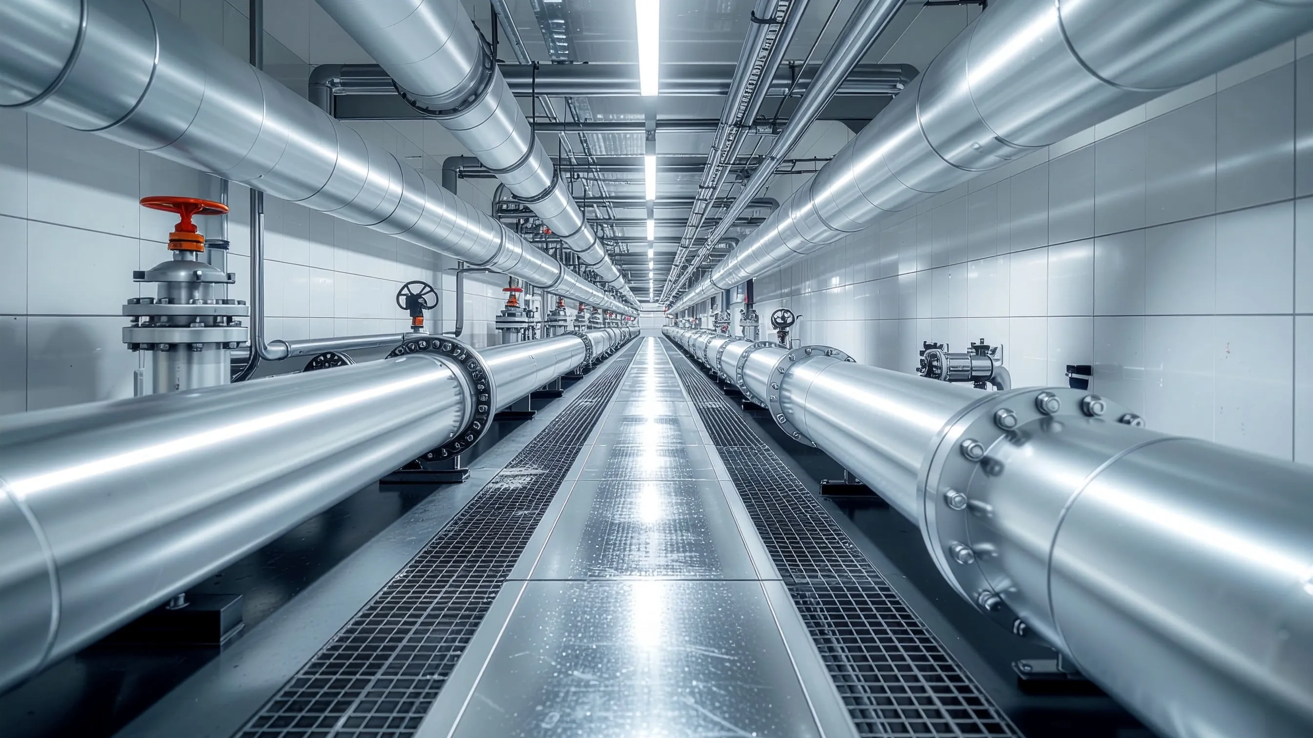
Commercial buildings with extensive hot water distribution networks face a persistent challenge. They must maintain water temperature at every outlet while preventing bacterial growth. Secondary return pipework provides the solution, creating a continuous circulation loop that keeps domestic hot water at safe temperatures throughout the system. Poor secondary return pipework design leads to temperature loss, energy waste, and potentially dangerous Legionella conditions.
The engineering principles behind effective secondary return systems combine thermal dynamics, hydraulic calculations, and regulatory compliance. Getting the design right from the outset prevents costly retrofits and ensures occupant safety across hotels, hospitals, office buildings, and multi-storey residential developments.
What Secondary Return Pipework Achieves
Secondary return pipework creates a circulation loop from the furthest draw-off points back to the DHW storage vessel or calorifier. This continuous flow maintains water temperature above 50°C throughout the distribution network. This prevents the 20°C to 45°C temperature range where Legionella bacteria multiply rapidly.
Without a return system, water in long pipe runs cools to ambient temperature between draw-offs. Users experience delayed hot water delivery, wasting water while waiting for the temperature to rise. More critically, stagnant tepid water creates ideal conditions for bacterial colonisation. The secondary return pipework addresses this directly by keeping the entire distribution network in continuous circulation. You can rely on National Pumps and Boilers to supply the right components to keep this loop efficient.
Think of secondary return pipework design like a city's ring road system. If traffic can only go down dead-end streets, cars get stuck and engines idle. A continuous loop keeps everything moving smoothly so that hot water arrives exactly when and where it is needed, without massive delays.
The strict BS 8558 temperature requirements specify that water temperature at the calorifier outlet should reach 60°C. Return temperatures must not fall below 50°C at the calorifier return inlet. This 10°C differential represents the maximum acceptable heat loss across the entire distribution network. Energy efficiency demands careful balancing. Excessive circulation wastes heat through pipe losses, while insufficient flow allows dangerous temperature drops.
Design Principles for Secondary Return Systems
Effective secondary return pipework design starts with accurate heat loss calculations. Engineers must account for pipe material, insulation thickness, ambient temperature, and pipe length to determine the heat dissipation rate along each circuit section returning to an andrew water heater or central cylinder.
The fundamental design rule limits temperature drop to 5°C on flow pipework and 5°C on return pipework under no-draw conditions. This ensures you meet the BS 8558 temperature requirements easily, keeping the 50°C minimum when flow leaves the plant at 60°C.
Pipe sizing follows a different methodology than standard flow pipework. Return pipes carry lower flow rates, typically 10-15% of the maximum draw-off flow rate. The sizing calculation must balance adequate velocity to prevent air accumulation against excessive pressure drop. Oversized return pipes increase heat loss surface area and reduce flow velocity. Both factors are detrimental to temperature maintenance and ultimately compromise your secondary return pipework design.
A branch balancing valve positioned on each return loop allows for individual circuit adjustment. The longest pipe run typically requires full valve opening, with shorter runs throttled to equalise return temperatures. This prevents short-circuiting where flow takes the path of least resistance.
When our technical support team helped a mechanical contractor at a newly commissioned 8-storey hotel, we discovered they had omitted a crucial branch balancing valve on the shortest ground-floor pipe run. The water took the path of least resistance, leaving the top floors starved of circulation. Installing the correct branch balancing valve instantly restored the required 50°C return temperature across all floors and resolved the tenant complaints overnight.
Circuit layout should minimise dead legs. Any branch serving a single outlet longer than 3 metres requires an individual return connection or trace heating. Implementing a ladder-type circulation layout helps prevent these dead legs by ensuring multiple return paths connect back to the main circuit.
Pump Selection and Positioning
The circulation pump must overcome total system head loss while delivering the calculated flow rate. Head loss calculations include friction losses in pipes, fittings, and valves, plus any static height difference if return pipework runs below the calorifier level.
A typical commercial secondary return system requires 0.3 bar to 0.6 bar pressure and flow rates between 10-30% of peak hot water demand. Look closely at the grundfos circulating pumps available to find dedicated DHW models with bronze or stainless steel construction. These ensure hot water compatibility throughout the system's service life.
Variable speed pumps with temperature feedback offer significant energy savings. The pump modulates speed to maintain the target temperature at the calorifier return inlet, reducing circulation during low-demand periods. Temperature sensors at the calorifier return inlet provide control feedback, automatically increasing pump speed if the temperature drops below the setpoint.
Twin pump installations provide redundancy for critical applications like hospitals or hotels where hot water interruption is unacceptable. Duty/standby arrangements with automatic changeover ensure continuous operation even during pump maintenance.
Compliance with British Standards
BS 8558:2015 provides comprehensive guidance for DHW services design, installation, and commissioning. The standard mandates secondary return circulation for any system where pipework from the heat source to the furthest outlet exceeds 12 metres in hospitals or 20 metres in other buildings.
Temperature monitoring points must be installed at the flow outlet, the calorifier return inlet, and sentinel taps representing the furthest points on each circuit. Monthly temperature checks verify system performance against BS 8558 temperature requirements and identify developing issues early.
Building Regulations Part L requires DHW systems to minimise heat loss through efficient distribution design and adequate insulation. Secondary return pipework must receive the same insulation specification as flow pipes. This usually means 25-40mm thickness depending on pipe diameter and location.
Healthcare facilities follow additional requirements under HTM 04-01, which specifies more stringent temperature control. In these clinical environments, return temperatures must not fall below 55°C at any monitored point to ensure maximum bacterial suppression. If you are running an ecoTEC commercial boiler, you must ensure secondary return connections incorporate approved backflow prevention devices to meet the Water Supply (Water Fittings) Regulations 1999.
Common Design Errors and Solutions
Undersized return pipes represent the most frequent design error. Engineers sometimes apply the same sizing methodology as flow pipes, resulting in excessive pressure drop and inadequate circulation. Return pipes should be one or two sizes smaller than equivalent flow pipes but never smaller than 15mm.
Incorrect branch balancing valve placement creates severe circulation problems. Valves installed on branch flows rather than returns cannot effectively balance the system. The balancing valve must sit on the return side of each circuit to control return flow without affecting supply pressure at outlets.
Missing or inadequate insulation on return pipework negates the entire system's purpose. Return pipes lose heat just as readily as flow pipes. Full insulation throughout both flow and return circuits is essential.
Complex building layouts often create unavoidable dead legs at distant single outlets. Rather than extending return pipework endlessly, trace heating provides a more economical solution. Electric trace heating maintains pipe temperature without requiring massive ladder-type circulation extensions.
Pump oversizing wastes energy and can cause noise issues through excessive velocity. A correctly sized building services circulator operates quietly and efficiently within its design envelope, delivering the required performance without unnecessary energy expenditure.
Installation Best Practices
Pipe installation must maintain continuous falls on return pipework to facilitate air venting. Air pockets in horizontal pipe runs prevent circulation and create cold spots. A minimum 1:100 gradient towards automatic air vents ensures trapped air can escape.
Expansion vessels sized for the total system volume accommodate thermal expansion in the DHW circuit. The vessel connects to the coldest part of the system, typically the return pipe before the circulation pump. Finding reliable heating system components ensures correct vessel sizing prevents pressure relief valve discharge during heat-up cycles.
Gate or ball valves on both sides of the pump allow removal for maintenance without draining the entire system. A check valve prevents reverse circulation through the pump when it stops. Specifying premium components often simplifies this, as many commercial units come with appropriate valve sets for straightforward secondary return installation.
Temperature and pressure test points at strategic locations enable commissioning verification. Test points should include the calorifier flow and return connections, plus the furthest point on each major branch in a ladder-type circulation network.
Maintenance and Monitoring
Monthly temperature monitoring at designated sentinel taps verifies continued system performance. Temperature readings below 50°C at any monitored point indicate balancing issues, pump problems, or excessive heat loss.
Annual balancing valve adjustment maintains optimal flow distribution as system conditions change. Building alterations, pipe scaling, or valve wear can shift flow patterns over time. Re-balancing ensures all circuits receive adequate circulation.
Pump performance checks include vibration monitoring, noise assessment, and power consumption measurement. Increasing power draw or unusual noise indicates bearing wear. If you suspect an issue, checking the system flow with a reliable pressure pump diagnostic tool ensures you catch problems before complete failure occurs.
Calorifier inspection and descaling on a schedule appropriate to water hardness prevents scale accumulation. Hard water areas may require annual descaling, while soft water locations might extend intervals to three years.
Conclusion: Professional Secondary Return Design
Secondary return pipework design demands a thorough understanding of hydraulic principles, heat transfer calculations, and regulatory requirements. Proper implementation maintains safe DHW temperatures throughout commercial buildings while preventing Legionella risks.
The critical design elements work together to create systems that perform reliably over decades of service. Accurate pipe sizing, appropriate pump selection, effective balancing, and comprehensive insulation are completely non-negotiable. Shortcuts in any area compromise the entire installation.
Professional specification and installation by experienced contractors ensures compliance with British Standards and Building Regulations. The upfront investment in proper design prevents costly retrofits and protects building occupants.
For expert guidance on DHW loop engineering and the supply of quality components for commercial systems, Send Us Your Enquiry to discuss specific project requirements.